Nitrogen rejection methods and systems

a technology of nitrogen and nitrogen, applied in the direction of refrigeration and liquidation, lighting and heating apparatus, solidification, etc., can solve the problems of increasing the area footprint and weight of the facilities involved, the nitrogen content of produced natural gas streams is one of the toughest energy challenges in the world, and the separation of nitrogen from methane is technically challenging

Inactive Publication Date: 2012-02-16
EXXONMOBIL UPSTREAM RES CO
View PDF9 Cites 17 Cited by
  • Summary
  • Abstract
  • Description
  • Claims
  • Application Information

AI Technical Summary

Benefits of technology

[0017]In yet another alternative embodiment, the method may include taking a reboiler feed stream from the separation unit; taking a slip stream from the substantially liquefied natural gas feed stream; exchanging heat energy from the slip stream to the reboiler feed stream in a reboiler heat exchanger to generate a nitrogen containing vapor from the reboiler feed stream; re-mixing the slip stream with the substantially liquefied natural gas feed stream; and maintaining a back-pressure on a feed condensing pass of the feed stream heat exchanger using an expansion device configured to receive the substantially liquefied natural gas fee

Problems solved by technology

The separation of nitrogen from methane is technically challenging because the gases have similar size, chemical nature, and boiling point.
The additional complexity of nitrogen separation and the compression normally associated with nitrogen removal from methane-rich streams combine to increase the area footprint and weight of the facilities involved.
Efficiently reducing the nitrogen content of produced natural gas streams is one of the world's toughest energy challenges.
This approach is very capital intensive as a lot of aluminum is needed.
Further, the final methane product is typically produced at low pressure, so re-pressurization is needed, which is almost always accomplished via ener

Method used


Image

  • Nitrogen rejection methods and systems
  • Nitrogen rejection methods and systems
  • Nitrogen rejection methods and systems

Examples


example

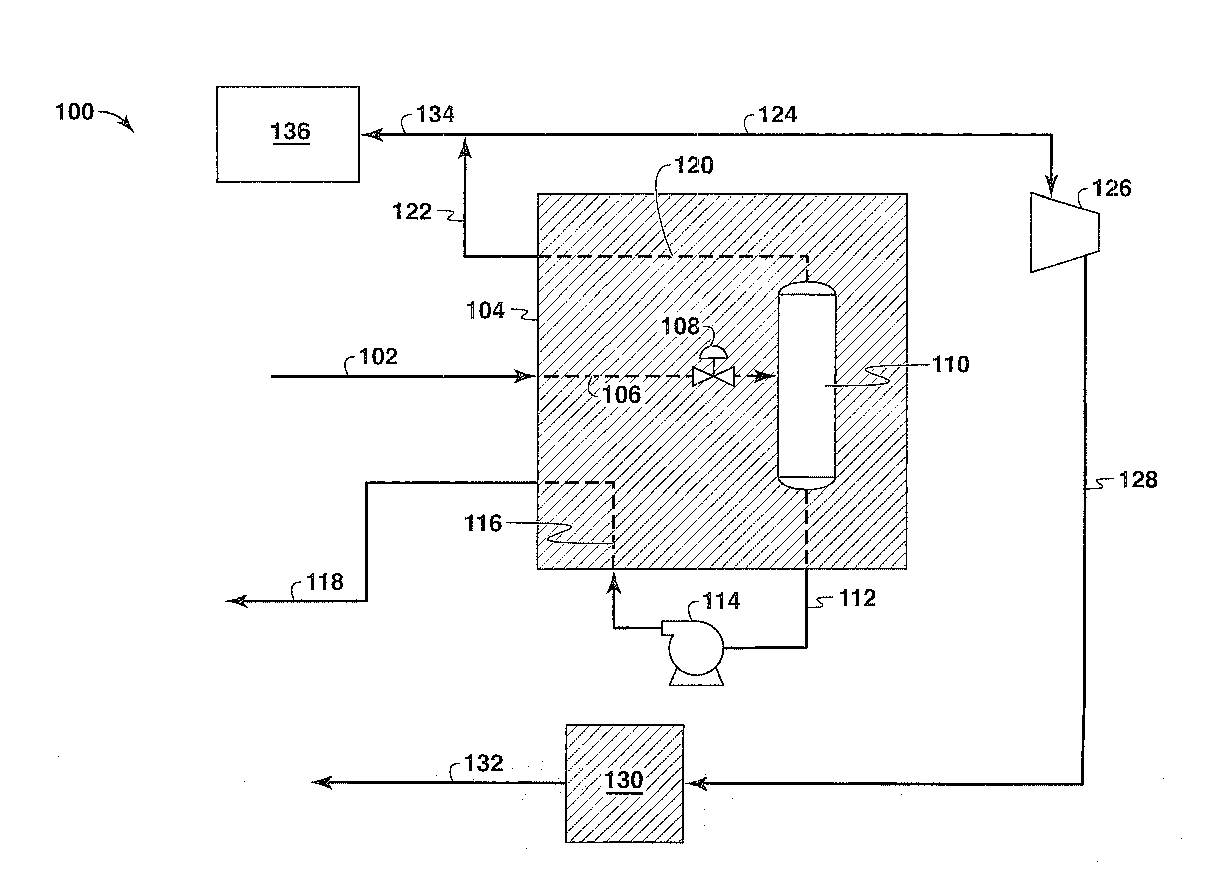
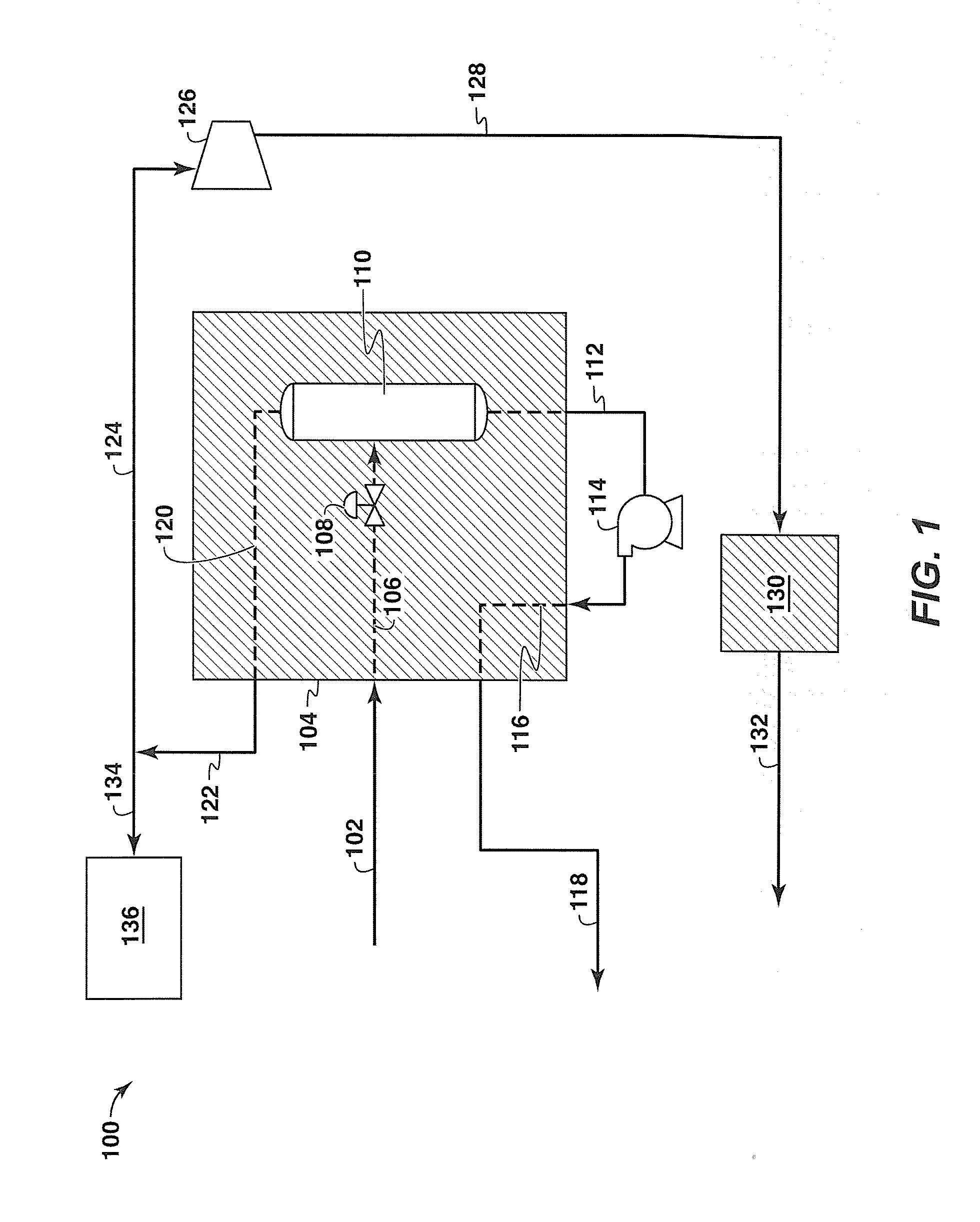
[0076]In one exemplary case, a natural gas feed stream having an assumed temperature, flow rate, pressure, and composition was provided. Table 1 below shows the temperature, flow rate, pressure, and composition of the relevant streams as shown in FIGS. 1 and 3A.

TABLE 1StreamStreamStreamStreamStreamStreamStreamStreamComponent102122118106306112120312methane0.9040.7750.9770.9040.9040.9650.7810.773nitrogen0.0930.2240.0200.0930.0930.0320.2190.227ethane0.0030.0010.0030.0030.0030.0030.0000.000Total1.0001.0001.0001.0001.0001.0001.0001.000Pressure915275770905902285280300(psia)Temperature136130130−131−150−170−176−174(deg F.)Mscfd9534619595771618

[0077]In particular, the exemplary flow rates illustrate the relative size of warmed nitrogen rich stream 122 as compared with the natural gas feed stream 102. Beneficially, this results in a smaller volume of fluids going to the NRU 130 for further treatment, lowering the energy consumption, footprint, materials, and capital costs of such systems and ...


PUM


Abstract

Methods and systems for removing nitrogen from a natural gas feed stream. The systems and methods generally include a heat exchange unit, a separation unit, and a liquid methane pump unit, where the separation unit produces a liquid methane bottoms stream and a gaseous overhead stream enriched in nitrogen and the liquid methane pump unit compresses the liquid methane bottoms stream and then pumps the stream through the heat exchange unit to cool a natural gas feed stream. In some embodiments the liquid methane pump unit is a sleeve bearing type unit. Beneficially, the disclosed systems and methods incorporate high head pumps for liquid methane compression instead of vaporizing the liquid methane and compressing it in a gaseous compression units that are typically used for this purpose, saving space, materials, and power.

Description

CROSS REFERENCE TO RELATED APPLICATIONS[0001]This application claims the benefit of U.S. Provisional Application No. 61 / 178,328 filed May 14, 2009.FIELD OF THE INVENTION[0002]Embodiments of the disclosed invention relate to nitrogen rejection methods and systems. More particularly, embodiments of the disclosed invention relate to methods and systems for efficiently reducing the nitrogen concentration of a natural gas production stream.BACKGROUND OF THE INVENTION[0003]This section is intended to introduce various aspects of the art, which may be associated with exemplary embodiments of the present disclosure. This discussion is believed to assist in providing a framework to facilitate a better understanding of particular aspects of the present disclosure. Accordingly, it should be understood that this section should be read in this light, and not necessarily as admissions of prior art.Description of the Related Art[0004]Natural gas is one of the world's fastest growing and most signi...

Claims


Application Information

Patent Timeline
IPC IPC(8): F25J3/00
CPCF25J3/0209F25J3/0233F25J3/0257F25J3/061F25J3/0635F25J3/066F25J2200/02F25J2200/70F25J2205/04F25J2230/42F25J2230/60F25J2235/60F25J2240/40F25J2260/60F25J2280/02F25J2290/42
Inventor KIMBLE, EDWARD LRASMUSSEN, PETER C
Owner EXXONMOBIL UPSTREAM RES CO
Why Eureka
Try Eureka