Method and system for exhaust gas recirculation control

a technology of exhaust gas recirculation and control method, which is applied in the direction of electric control, machines/engines, mechanical equipment, etc., can solve the problems of engine performance and engine emissions degradation, transient changes in torque, and delay in providing the desired egr flow, so as to reduce exhaust emissions and improve fuel economy

Active Publication Date: 2012-02-16
FORD GLOBAL TECH LLC
View PDF31 Cites 84 Cited by
  • Summary
  • Abstract
  • Description
  • Claims
  • Application Information

AI Technical Summary

Benefits of technology

[0002]In an effort to meet stringent federal government emissions standards, Engine systems may be configured with exhaust gas recirculation (EGR) systems wherein at least a portion of the exhaust gas is recirculated to the engine intake. Such EGR systems enable reduction in exhaust emissions while also improving fuel economy. Various sensors may be included in the engine system to estimate the EGR flow and control an amount of EGR delivered to the engine intake.
[0007]The percent dilution of the EGR flow, at and beyond the mixing point, may be inferred from the output of an oxygen sensor positioned in the engine intake gas stream, downstream of the mixing point of the EGR valve and the first intake throttle, and upstream of a second main intake throttle. An engine controller may be configured to estimate a percent dilution based on feedback from the oxygen sensor output using a model that accounts for delays in dilution propagation of EGR flow from the mixing point to the engine intake point. For example, the model may compensate for relatively long delays between EGR valve (and first throttle) actuation and observed changes in dilution concentration at the oxygen sensor.
[0008]Thus, based on the oxygen sensor output voltage, an amount of EGR available (flow rate, amount, dilution, etc.) may be determined. Based on engine operating conditions, an amount of EGR desired may also be determined. The engine controller may then adjust the EGR valve and the first air intake throttle responsive to the output of the oxygen sensor, for example, based on feedback information regarding the available amount of EGR, inferred from the oxygen sensor output, and feed-forward information regarding the position of the EGR valve and the first intake throttle, to provide the desired amount of EGR. In one example, the adjustment may include, in response to the oxygen sensor output indicating EGR dilution is higher than a threshold, closing the EGR valve to provide less burned exhaust gas in the EGR, while opening the first air intake throttle to increase the amount of fresh air dilution of EGR. The adjustments of the EGR valve may be coordinated, for example, simultaneously or sequentially, with the adjustments of the first air intake throttle. In one example, as the EGR valve is opened, the first air intake throttle may be simultaneously proportionally closed. In another example, the first air intake throttle may start closing only after the EGR valve has crossed a threshold position. In still other examples, the adjustments may be modified based on positional limits of the EGR valve and the first intake throttle. For example, when the EGR valve is limited, or is in a non-linear region of operation, the desired EGR flow may be largely controlled by the first air intake throttle, and when the first air intake throttle is limited, or in a non-linear region of operation, the desired EGR flow may be largely controlled by the EGR valve. In this way, by adjusting both the EGR valve and the first air intake throttle in response to the output of the oxygen sensor, a faster and more precise EGR flow control may be obtained.
[0009]Further still, the adjustments of the EGR valve and the first air intake throttle may be coordinated with adjustments of a second main intake throttle, positioned downstream of the first air intake throttle, to reduce transient torque disturbances resulting from the EGR valve and first intake throttle adjustments. Specifically, the second main intake throttle may be adjusted responsive to the output of the oxygen sensor to maintain a desired engine torque. In one example, the adjustment of the second main intake throttle may follow the adjustment of the EGR valve and the first air intake throttle by a delay time to compensate for propagation delays.
[0010]In this way, EGR valve and first air intake throttle adjustments may be coordinated to provide the desired amount of EGR rapidly and accurately, while main intake throttle adjustments may be used to provide the desired torque even during the EGR valve and first air intake throttle adjustments. Further, the control and coordination of the distributed valves and throttles may be improved. By using adjustments to both an EGR valve and an first air intake throttle to provide the desired EGR flow, EGR flow adjustments may be possible even when one of the actuators is limited, or is within a non-linear region of operation. Additionally, by using the output of a single oxygen sensor to perform all the adjustments, the use of multiple sensors (such as air-flow sensors, exhaust air-fuel ratio sensors, pressure sensors etc.) in determining EGR dilution may be reduced, thereby providing component and cost reduction benefits, without degrading system precision.

Problems solved by technology

However, the inventors herein have recognized potential issues with such a system.
Due to the distributed position of EGR valves and throttles in engine systems such as the engine system of Tonetti, EGR valve adjustments made in response to the output of the oxygen sensor may be relatively slow leading to a delay in providing the desired EGR flow.
EGR valve adjustments may also cause transient changes in torque that may need to be compensated for.
Delays and insufficiencies in EGR flow may lead to degraded engine performance and engine emissions.

Method used


Image

  • Method and system for exhaust gas recirculation control
  • Method and system for exhaust gas recirculation control
  • Method and system for exhaust gas recirculation control

Examples


Embodiment Construction

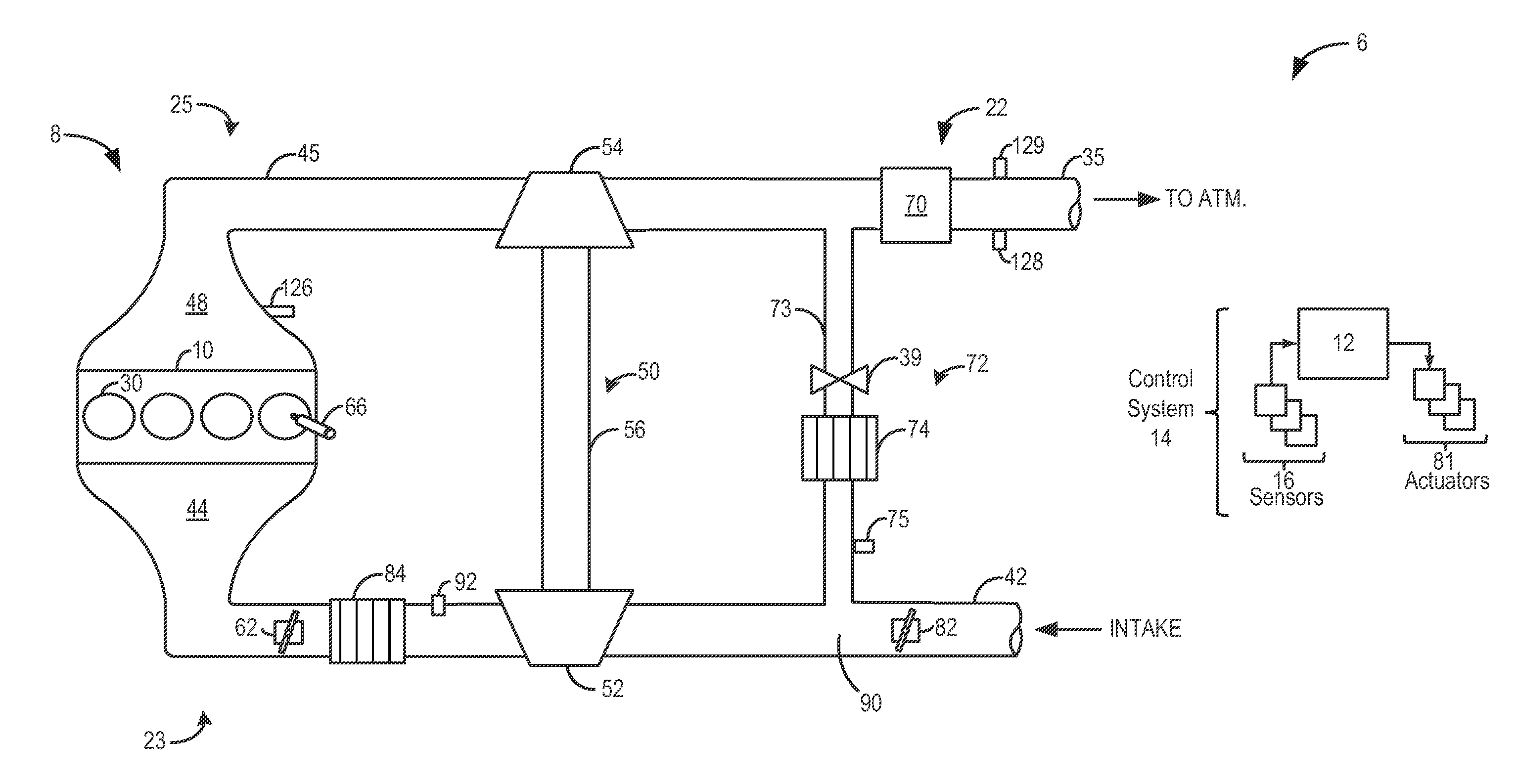
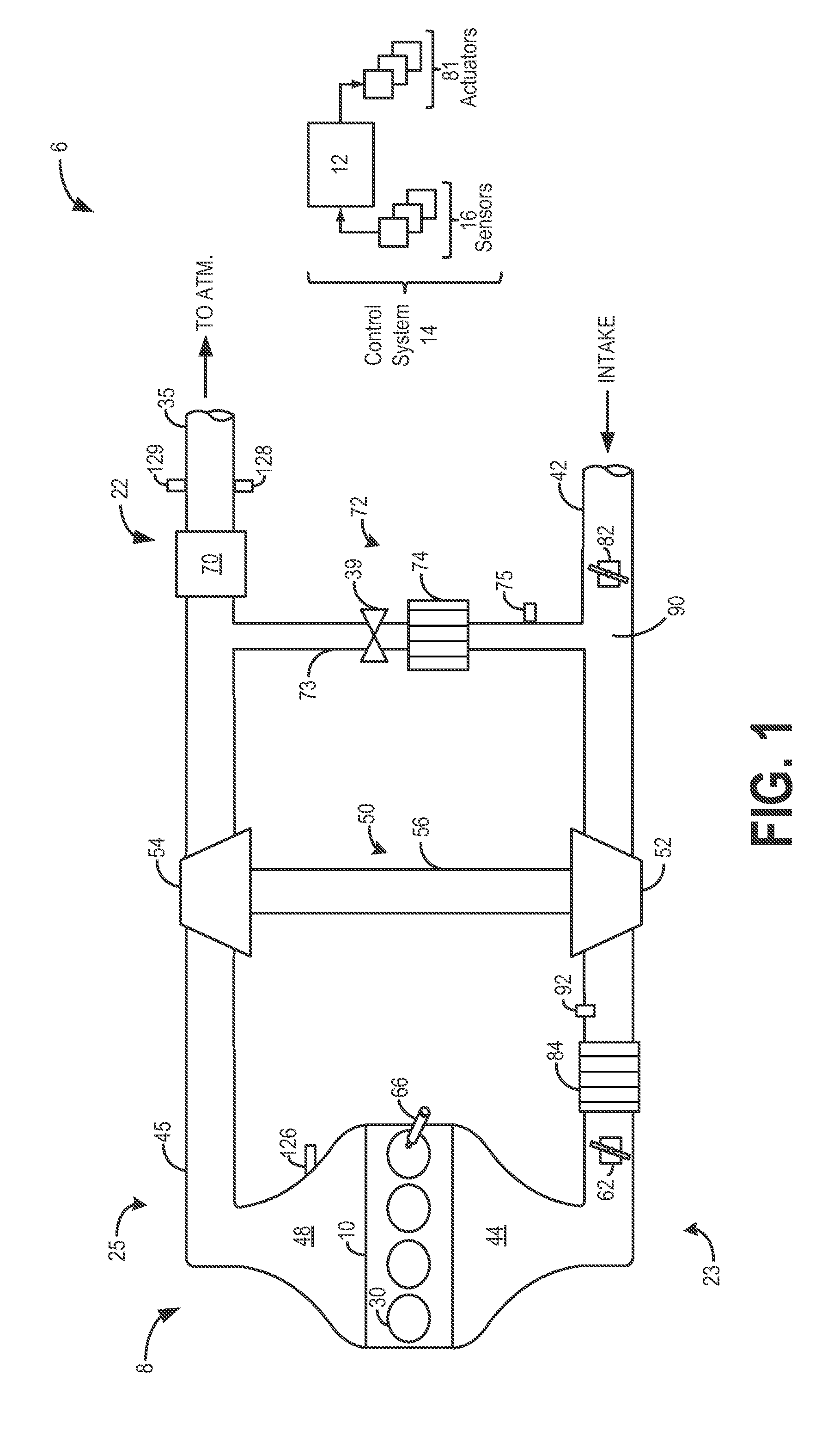
[0016]The following description relates to systems and methods for controlling dilution of exhaust gas for exhaust gas recirculation based on the output of an intake oxygen sensor. As shown in FIG. 1, a boosted engine may be configured with a low-pressure exhaust gas recirculation (EGR) system that may include an EGR valve for adjusting an amount of exhaust gas recirculated to the engine intake. The engine may further include a plurality of intake throttles including at least a first and second intake throttle coupled to the engine intake, the throttles configured to adjust an amount of fresh air directed to the engine intake. Specifically, the first, upstream, air intake throttle may adjust an amount of fresh air diluted with the exhaust gas in the EGR flow, while a second main intake throttle, downstream of the first air intake throttle and the EGR valve, may adjust the flow of an intake gas stream entering the engine intake. An oxygen sensor coupled to the engine intake may be co...


PUM


Abstract

Methods and systems are provided for adjusting an EGR valve and one or more intake throttles responsive to the output of an intake oxygen sensor to provide a desired amount of EGR flow while maintaining engine torque. The adjustments are coordinated to improve distributed control of the EGR valves and intake throttles, and enable EGR flow even when one actuator is limited.

Description

FIELD[0001]The present application relates to methods and systems for controlling exhaust gas recirculation in an engine system.BACKGROUND AND SUMMARY[0002]In an effort to meet stringent federal government emissions standards, Engine systems may be configured with exhaust gas recirculation (EGR) systems wherein at least a portion of the exhaust gas is recirculated to the engine intake. Such EGR systems enable reduction in exhaust emissions while also improving fuel economy. Various sensors may be included in the engine system to estimate the EGR flow and control an amount of EGR delivered to the engine intake.[0003]One example of such an EGR system is illustrated by Tonetti et al. in U.S. Pat. No. 7,267,117. Herein, an oxygen sensor is included in the engine air intake, and based on the output of the oxygen sensor, a controller is configured to adjust the position of an EGR valve to thereby provide a desired amount of EGR.[0004]However, the inventors herein have recognized potential...

Claims


Application Information

Patent Timeline
Patent Type & Authority Applications(United States)
IPC IPC(8): F02B47/08
CPCF02D41/0002F02D41/0072F02D41/144F02D2041/0017F02D2041/1431F02D2041/1432Y02T10/42Y02T10/47F02M26/06F02M26/47Y02T10/40
Inventor JANKOVIC, MRDJAN J.BUCKLAND, JULIE HELENKARNIK, AMEY Y.STYLES, DANIEL JOSEPH
Owner FORD GLOBAL TECH LLC
Why Eureka
Try Eureka