Output device for power tool having protection mechanism

a protection mechanism and output device technology, applied in power driven tools, construction, foundation engineering, etc., can solve the problems of interference between the stationary ratchet teeth of the stationary ratchet gear and the movable ratchet gear fixed on the output sha

Active Publication Date: 2012-02-16
TRINITY PRECISION TECH
View PDF5 Cites 7 Cited by
  • Summary
  • Abstract
  • Description
  • Claims
  • Application Information

AI Technical Summary

Benefits of technology

[0007]A primary objective of the present invention is to provide an output device for a power tool which overcomes the disadvantage of the conventional designs and protect parts of the device from damage due to the stress. The output device has ratchet gears. When the output shaft is rotated in the forward direction (unrestricted direction of the ratchet teeth), the output modes of the power tool include pure rotation and rotation combined with vibration in the axial direction. When the output shaft is rotated in the reverse direction (restricted direction of the ratchet teeth), the axial vibration function is automatically released and the output mode includes pure rotation only so as to protect the inner parts of the output device.
[0008]The characteristic of the present invention is that an output device for a power tool includes a protection mechanism to protect the inner parts of the output device. The output device comprises a stationary ratchet gear having multiple ribs and each rib includes an inclined surface, and a locking member having at least one pawl. A control device controls the pawl to be engaged with or disengaged from the ribs of the stationary ratchet gear. When the pawl is not engaged with the ribs of the stationary ratchet gear, the stationary ratchet gear is free to rotate. When an axial force is applied to the output shaft to engage the movable ratchet gear with the stationary ratchet gear, the output shaft outputs power in the form of rotation in the forward direction or the reverse direction. When the pawl of the locking member is engaged with the ribs of the stationary ratchet gear, the stationary ratchet gear is fixed and cannot rotate. In this situation, if an axial force is applied to the output shaft to engage the movable ratchet gear with the stationary ratchet gear and the output shaft is driven to rotate in the forward direction, the movable ratchet teeth of the movable ratchet gear fixed on the output shaft is interfered with the stationary ratchet teeth of the stationary ratchet gear. Therefore, the output shaft outputs rotation in the forward direction and vibration. When the pawl is engaged with the ribs, an axial force is applied to the output shaft to engage the movable ratchet gear with the stationary ratchet gear and the output shaft is driven to rotate in the reverse direction, the pawl engaged with the rib would slip away from the rib along the inclined surface. Thus, the stationary ratchet gear is disengaged from the movable ratchet gear. The stationary ratchet gear is no longer fixed. Therefore, the stationary ratchet gear can rotate with the output shaft and the movable ratchet gear in the reverse direction and without axial vibration. By this protection mechanism, the movable ratchet teeth and the stationary ratchet teeth are protected from damage due to the high stress.

Problems solved by technology

In this situation, if an axial force is applied to the output shaft to engage the movable ratchet gear with the stationary ratchet gear and the output shaft is driven to rotate in the forward direction, the movable ratchet teeth of the movable ratchet gear fixed on the output shaft is interfered with the stationary ratchet teeth of the stationary ratchet gear.

Method used


Image

  • Output device for power tool having protection mechanism
  • Output device for power tool having protection mechanism
  • Output device for power tool having protection mechanism

Examples


Embodiment Construction

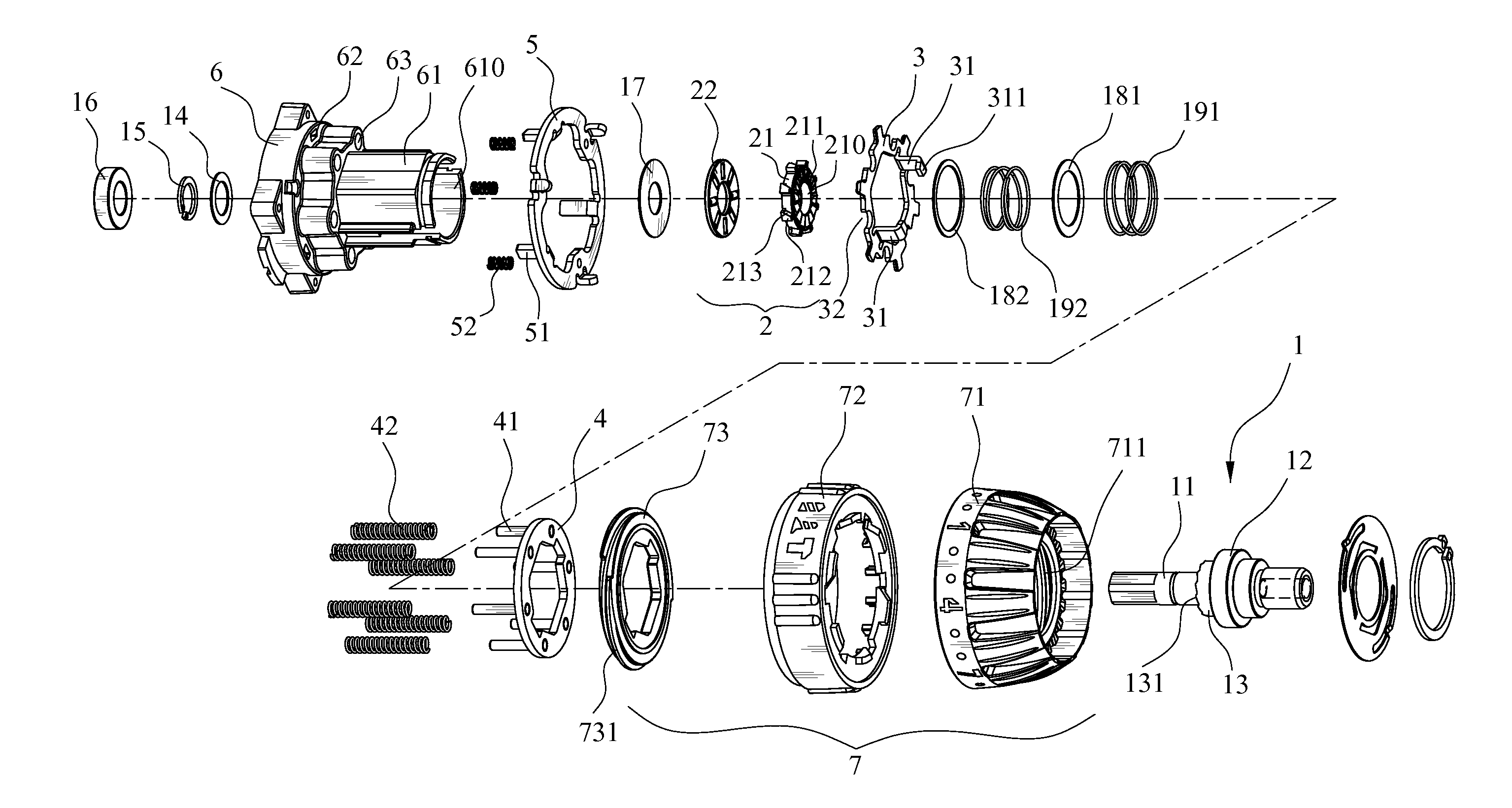
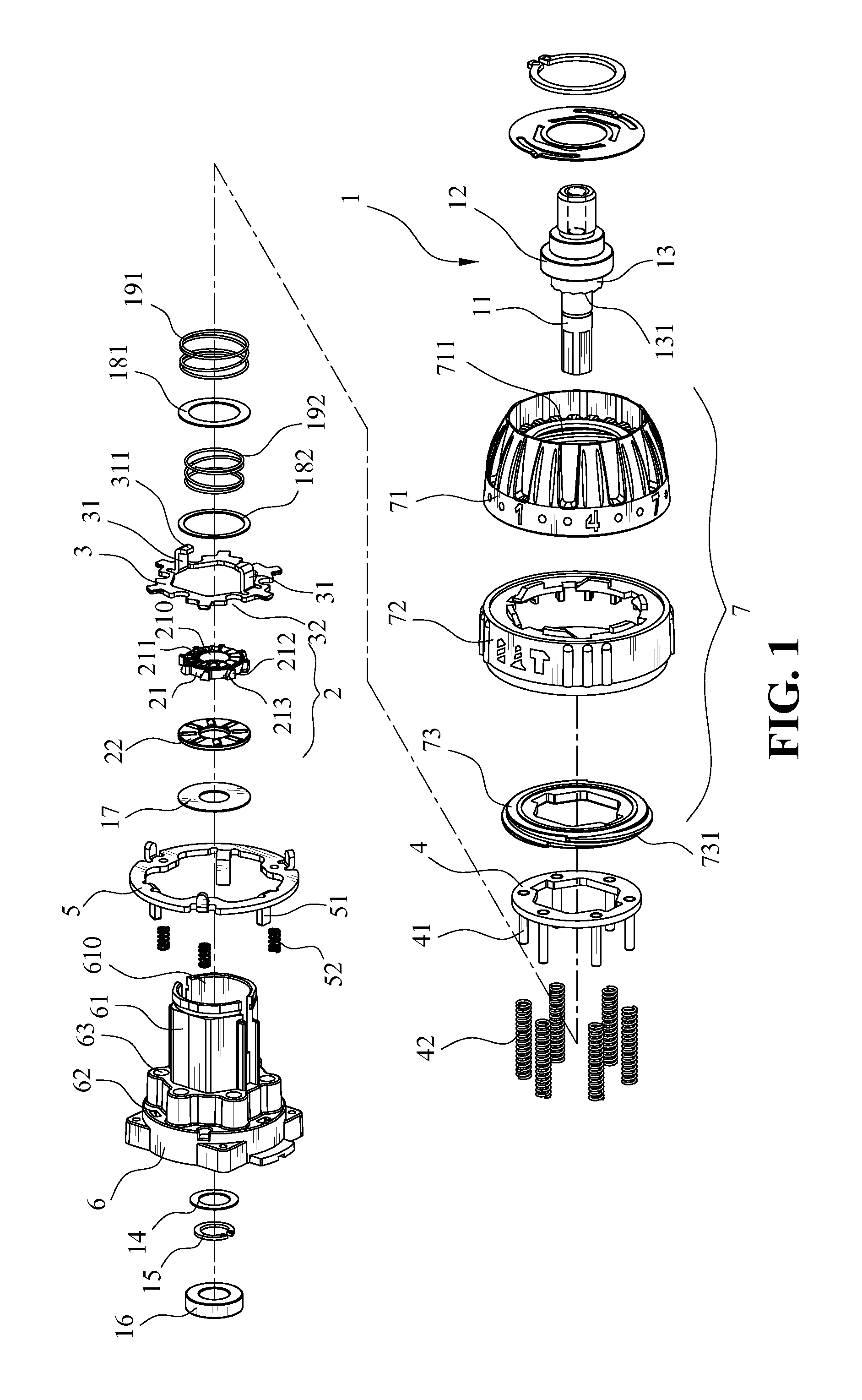
[0016]With reference to the drawings and in particular to FIG. 1, an output device for a power tool which has a protection mechanism in accordance with the present invention can provides output of rotation in the forward direction, rotation in the reverse direction and rotation in the forward direction combined with axial vibration. When the output is switched to rotation in the reverse direction, the axial vibration function is automatically relieved and the output is in the mode of rotation in the reverse direction without axial vibration. Therefore, inner parts of the output device are protected from damage due to the high stress.

[0017]With reference to FIG. 1, the output device for the power tool according to the present invention comprises an output unit 1, a stationary ratchet gear unit 2, a locking member 3, a spring washer 4, a positioning washer 5, a case 6 and a control unit 7. The output unit 1 comprises an output shaft 11, a first bearing 12 and a movable ratchet gear 13...


PUM


Abstract

An output device for a power tool includes an output unit, a stationary ratchet gear unit, a spring disposed between the output shaft unit and the stationary ratchet gear unit, a locking member having pawls, a case accommodating the aforementioned parts and a control device threadedly connected to the case. The output unit includes an output shaft with a first bearing and a movable ratchet gear which have movable ratchet teeth facing stationary ratchet teeth of a stationary ratchet gear. The stationary ratchet gear includes ribs and each rib has an inclined surface. When the pawls are not engaged with the ribs, the output shaft can outputs power in a form of rotation in both directions. When the pawls are engaged with the ribs, the output shaft outputs power in a form of rotation in a forward direction combined with vibration or rotation in a reverse direction without vibration.

Description

BACKGROUND OF THE INVENTION[0001]1. Field of the Invention[0002]The present invention relates generally to an output device for a power tool which can output pure rotation, rotation in the forward direction and axial vibration or rotation in the reverse direction without axial vibration, so as to protect a ratchet gear of the output device from damage.[0003]2. The Prior Arts[0004]A conventional power tool, such as a power drill, generally outputs power from the motor to the output shaft by the gear unit. Besides, in order to tighten the bolts or to loosen the bolts, some power tools are equipped with an axial vibration function which can output an impact force to tighten the bolts or loosen the bolts.[0005]The conventional impact power tool with the vibration function generally comprises an output shaft, a stationary ratchet gear and a movable ratchet gear mounted to the output shaft, at least one block located between the stationary ratchet gear and the movable ratchet gear, a case...

Claims


Application Information

Patent Timeline
Patent Type & Authority Applications(United States)
IPC IPC(8): B25F5/00
CPCB25B21/02
Inventor YIN, HSIN-CHIEH
Owner TRINITY PRECISION TECH
Why Eureka
Try Eureka