Free-mass and interface configurations of hammering mechanisms

a technology of hammering mechanism and free-mass, which is applied in the direction of percussive tools, manufacturing tools, portable drilling machines, etc., can solve the problems of system failure, system failure to disassemble, and termination of usdc operation, so as to minimize reduce the jamming of the free-mass portion, and maximize the impact momentum

Inactive Publication Date: 2012-02-16
CALIFORNIA INST OF TECH
View PDF1 Cites 8 Cited by
  • Summary
  • Abstract
  • Description
  • Claims
  • Application Information

AI Technical Summary

Benefits of technology

[0009]In one embodiment, the geometry of the free-mass portion is configured to reduce jamming of the free-mass portion as it moves from a position of contact with one of the horn portion and the bit portion to a position of contact with the other of the horn portion and the bit portion. In another embodiment, the geometry of the free-mass portion has a toroidal shape. In an additional embodiment, a contact profile when the free-mass portion is in the position of contact with one of the horn portion and the bit portion is chosen from the group consisting of a point contact, a circular contact, a line contact, a ring contact, a dashed line contact, a dashed ring contact, and combinations thereof In a further embodiment, the contact profile for the free-mass for the horn portion is different from the contact profile for the free-mass for the bit portion. In yet another embodiment, the free-mass portion is configured to maximize a stress amplitude at at least one of a first interface between said horn portion and said free-mass portion and a second interface between said free-mass portion and said bit portion without exceeding stress and material deformation parameters of said bit portion, said free-mass portion or said horn portion. In yet an additional embodiment, the free-mass portion has a material property chosen from at least one of a stiffness, a hardness, and a density. In yet a further embodiment, the free-mass portion has a mass configured to receive momentum from the horn portion and to transmit momentum to the bit portion without exceeding stress and material deformation parameters of the bit portion, the free-mass portion or the horn portion. In still another embodiment, the geometry of the free-mass portion is configurable to control a resonant frequency of the free-mass. In still an additional embodiment, the geometry of the free-mass portion is configurable to maximize impact momentum transferred from the horn portion to the bit portion. In still a further embodiment, the geometry of the free-mass portion is configurable to minimize the jamming of the free-mass portion. In still a further embodiment, the free-mass portion has a thickness configured to receive momentum from the horn portion and to transmit momentum to the bit portion without exceeding stress and material deformation parameters of the bit portion, the free-mass portion or the horn portion. In yet still another embodiment, the free-mass portion has a first resonant frequency, the horn portion has a second resonant frequency, and the bit portion has a third resonant frequency, the first resonant frequency being different from the second resonant frequency and the third resonant frequency. In yet still an additional embodiment the free-mass is constrained in a transverse direction and is free to move in an axial direction.

Problems solved by technology

This design has at least the problem that the free-mass tends to jam.
This results in the termination of operation of the USDC.
In addition once jammed, the system is difficult to disassemble.

Method used


Image

  • Free-mass and interface configurations of hammering mechanisms
  • Free-mass and interface configurations of hammering mechanisms
  • Free-mass and interface configurations of hammering mechanisms

Examples


Embodiment Construction

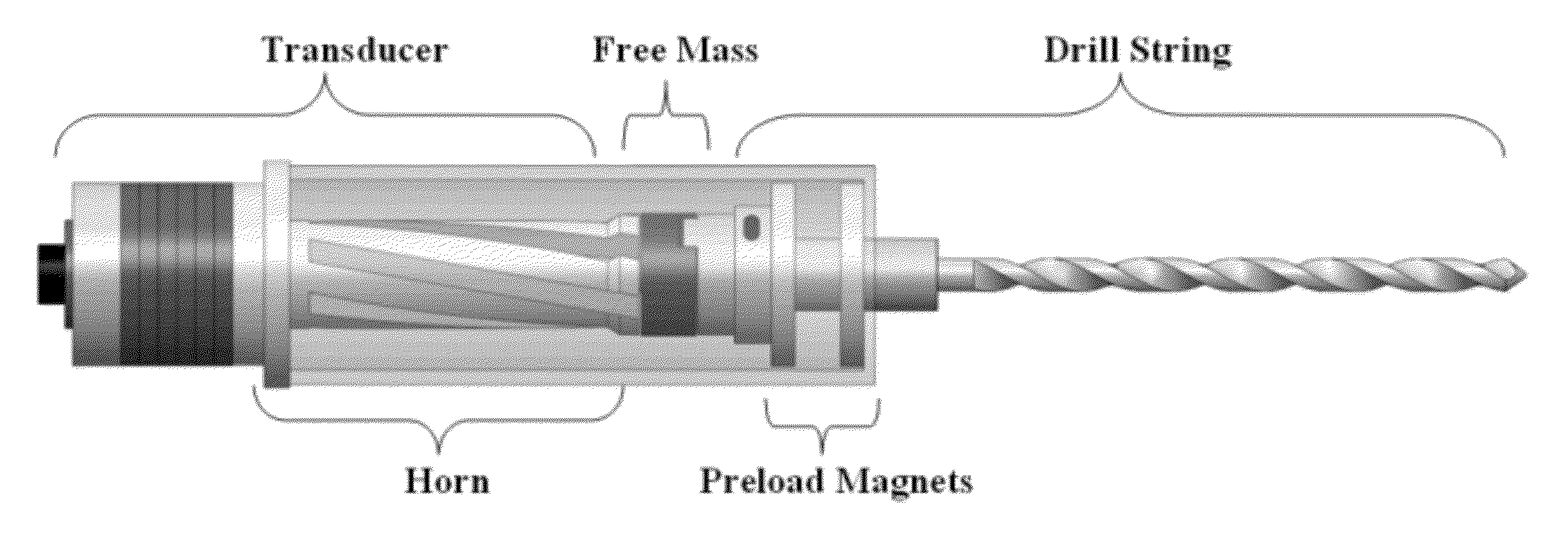
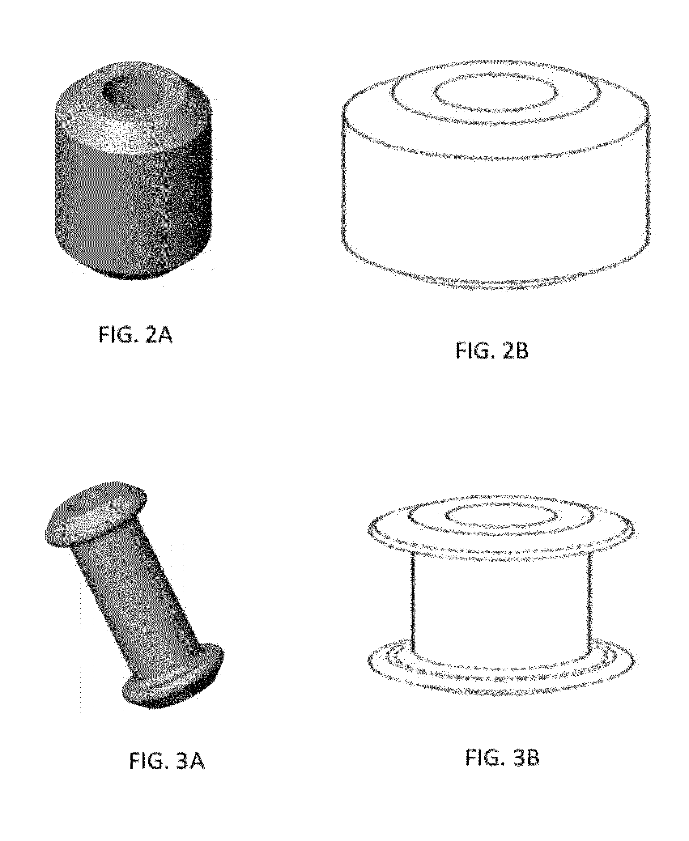
[0035]According to the principles of the present invention, the design of the free-mass in an ultrasonic driller / corer (USDC) has been refined in order to improve the performance and operational reliability of the system. In one embodiment, the improvements in performance and operational reliability include decreasing the impact surface area of the free-mass to increase the transfer of impact energy from the piezoelectric transducer and shaping the free-mass to reduce the likelihood that the system will jam.

[0036]The operation of a USDC includes an actuation material, such as a piezoelectric or electrostrictive material, that is mechanically coupled to an ultrasonic horn. The ultrasonic horn receives ultrasonic vibrational energy and amplifies or otherwise modifies the energy, for example by focusing the energy at a particular location and / or by imparting directionality to the forces that the actuation material provides (for example, by converting linear motion to rotational motion)...


PUM

PropertyMeasurementUnit
temperaturesaaaaaaaaaa
frequencyaaaaaaaaaa
weightsaaaaaaaaaa

Abstract

The design of the free-mass in an ultrasonic driller/corer (USDC) has been refined in order to improve the performance and operational reliability of the system. In one embodiment, the improvements in performance and operational reliability include decreasing the impact surface area of the free-mass to increase the transfer of impact energy from the piezoelectric transducer and reductions in the likelihood that the system will jam.

Description

CROSS-REFERENCE TO RELATED APPLICATIONS[0001]This application claims priority to and the benefit of co-pending U.S. provisional patent application Ser. No. 61 / 407,159 filed Oct. 27, 2010 and this application is also a continuation-in-part of co-pending U.S. patent application Ser. No. 12 / 877,390 filed Sep. 8, 2010, which application claimed priority to and the benefit of then co-pending U.S. provisional patent application Ser. No. 61 / 240,569 filed Sep. 8, 2009. This application is related to U.S. patent application Ser. No. 11 / 700,575 filed Jan. 31, 2007. Each of the applications referenced above is incorporated herein by reference in its entirety.STATEMENT REGARDING FEDERALLY FUNDED RESEARCH OR DEVELOPMENT[0002]The invention described herein was made in the performance of work under a NASA contract, and is subject to the provisions of Public Law 96-517 (35 USC 202) in which the Contractor has elected to retain title.FIELD OF THE INVENTION[0003]The invention relates to ultrasonic dr...

Claims


Application Information

Patent Timeline
Patent Type & Authority Applications(United States)
IPC IPC(8): B23B45/16
CPCB23B37/00B23B2260/108E21B1/02E21B25/00
Inventor BAO, XIAOQISHERRIT, STEWARTBADESCU, MIRCEABAR-COHEN, YOSEPHASKINS, STEVEOSTLUND, PATRICK
Owner CALIFORNIA INST OF TECH
Why Eureka
Try Eureka