
RFID proximity card holder with flux directing means

a technology of magnetic flux and proximity card holder, which is applied in the field of magnetic flux directing means for proximity card holder, can solve the problems of unable to power and use the proximity card, unable to achieve the proper positioning of the proximity card relative to the lines of flux generated by the reader, and unable to achieve the proper positioning of the proximity card in real-world operation

Inactive Publication Date: 2012-02-16
HOURANI FRED
View PDF3 Cites 8 Cited by
  • Summary
  • Abstract
  • Description
  • Claims
  • Application Information

AI Technical Summary

Problems solved by technology

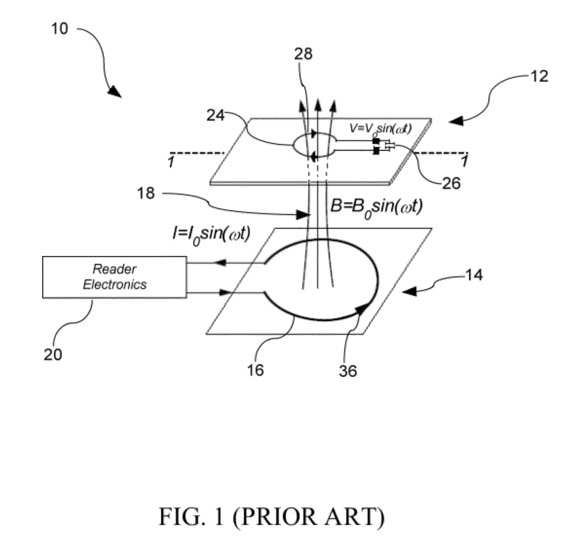
However, one drawback associated with such near field wireless energy transmission is that a sufficient electromagnetic flux passing through the card antenna coil necessary to power the smartcard electronics is only obtained when the proximity card has a well defined orientation relative to the flux lines generated by the reader.
When the position of the proximity card is deviated from this optimal orientation, the flux passing through the area of a card antenna loop rapidly decreases thereby rendering the proximity card powerless and useless until a sufficient orientation is found.
Proper positioning of a proximity card relative to the lines of flux generated by a reader may be especially difficult to attain and maintain in real world operation, such as in mass transit wherein commuters position cards over a reader at various angles with their hands or position bags and purses containing such cards.
This drawback presents serious repercussions, notably regarding high volume transaction situations, for example at mass transit contactless card reader stations located on bus or subway access points, wherein recognition of an RFID proximity card is needed to be accomplished in the shortest amount of time.
Prolonged reading times at a contactless card reader station due to improper card orientation or distance has a compounding effect when multiple cards experience such problems, leading to increases in boarding times and ultimately disgruntle commuters.
Such integration, however, increases the fabrication costs, bulkiness, and weight of a RFID proximity card.
However, due to the high failure rate of proximity cards, integrating magnetic material within the substrate of a proximity card may be costly, particularly for the mass transportation market where cards are easily lost and fail regularly due to the abuse endured from daily handling.
Such a bond is prone to breakage should a card be subjected to excessive bending and torsion flexing when, notably, card holders attempt to use their card by pressing the card on a card reader, and from the daily handling and storing of a card in a purse, pocket, wallet, bag, or the like.
Therefore, these factors may impact or significantly reduce the readability and life span of an RFID proximity smartcard.

Method used


Image

  • RFID proximity card holder with flux directing means
  • RFID proximity card holder with flux directing means
  • RFID proximity card holder with flux directing means

Examples


Embodiment Construction

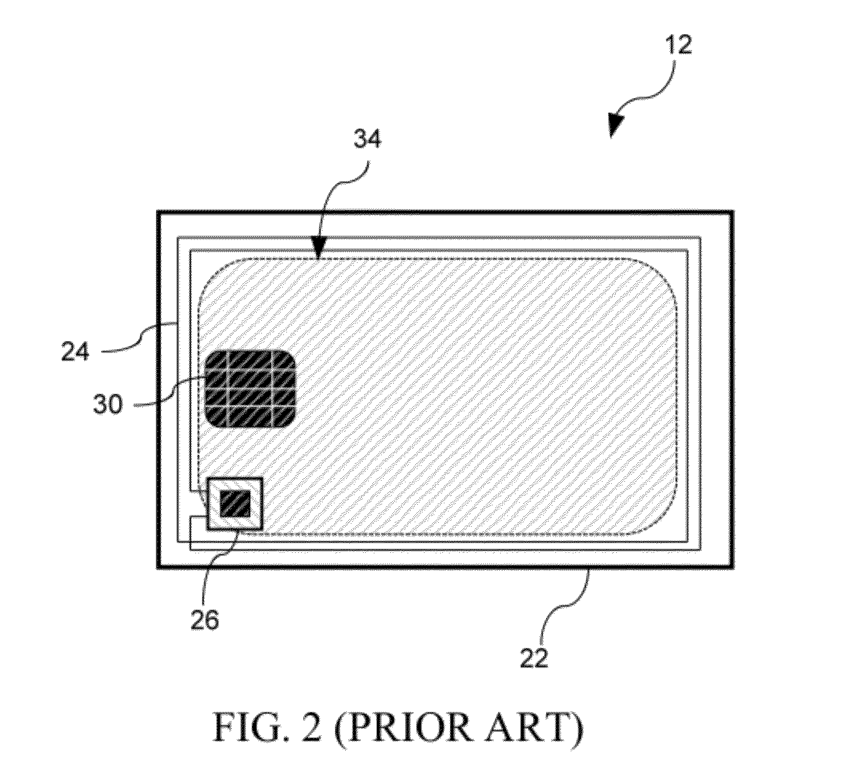
[0020]Referring to FIG. 1, a contactless smartcard system in accordance with an illustrative embodiment of the present invention, generally referred to using the reference number 10 is described. In particular, the contactless smartcard system 10 comprises an RFID proximity card 12 and a contactless interface 14, also generally known in the art as a card reader or a card interrogator, for powering and communicating with the proximity card 12. Generally, the reader 14 comprises a reader antenna coil 16 that provides energy in the form of a generated magnetic flux 18 and / or for communication with an RFID proximity card 12 when brought into proximity with the reader 14, as well as electronics 20 to process validation and other information transmitted from the RFID proximity card 12. In accordance with the illustrative embodiment of the present invention, when the contactless smartcard system 10 is used for public transit applications, the reader 14 is commonly located in fare boxes, ti...


PUM


Abstract

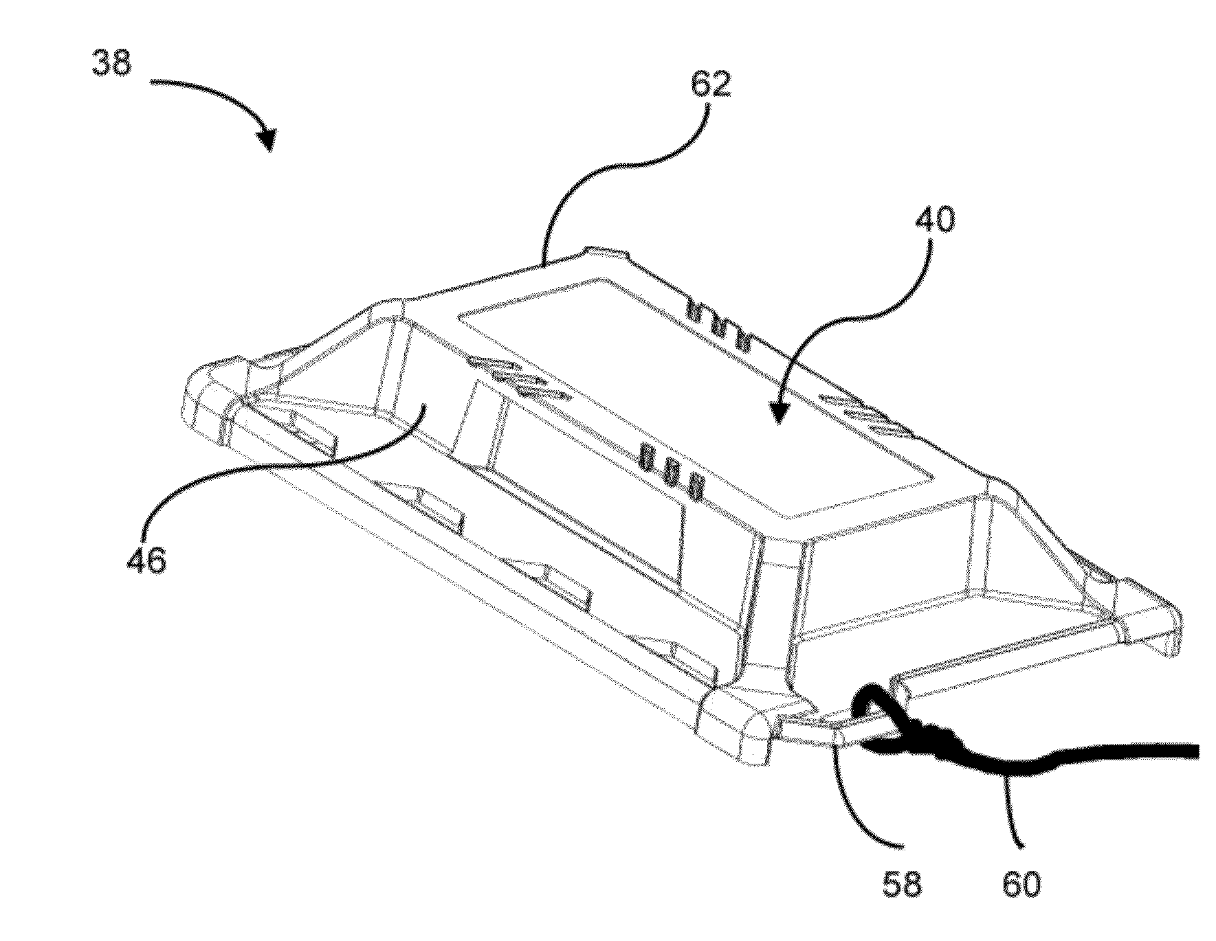
A card holder for an RFID proximity card having a coil loop antenna with an area for interfacing with a flux generating RFID proximity card reader. The card holder includes a flux directing means; and a housing for containing the flux directing means and receiving the RFID proximity card. When the RFID proximity card is received within the housing, the flux directing means influences the flux generated by the RFID proximity reader such that the flux is directed to within the area of the coil loop antenna.

Description

FIELD OF THE INVENTION[0001]The present invention relates to an RFID proximity card holder with magnetic flux directing means. In particular, there is provided an RFID proximity card holder comprising a magnetic flux directing means having a magnetic material for directing magnetic flux generated by a contactless interface to within the area of an RFID proximity card antenna loop.BACKGROUND OF THE INVENTION[0002]RFID proximity cards, or contactless smartcards, have become a widely used form of contactless rechargeable type smartcard for intelligent access control and payment systems, particularly in the area of mass public transportation, where fast transactions and ease of handling are desired. The prevalent type of contactless smartcards used for such systems are generally powered by and communicate with a contactless interface, or a proximity card reader, according to resonant energy transfer operating principles. In particular, such near field wireless transmission of energy ope...

Claims


Application Information

Patent Timeline
IPC IPC(8): G06K7/01
CPCG06K7/10336
Inventor HOURANI, FRED
Owner HOURANI FRED
Learn More