Tool holder

Active Publication Date: 2012-02-16
HILTI AG
View PDF24 Cites 8 Cited by
  • Summary
  • Abstract
  • Description
  • Claims
  • Application Information

AI Technical Summary

Benefits of technology

[0007]The forces that occur during impact are introduced to the shaft essentially over the entire circumference of the eye. This may result in low levels of stress to the materials.
[0008]The end piece preferably has a larger cross-section than the shaft between the end pieces. The tool hold

Problems solved by technology

This may result in low level

Method used


Image

  • Tool holder
  • Tool holder
  • Tool holder

Examples


Example

[0014]Unless otherwise indicated, the same or functionally equivalent elements are identified by the same reference characters in the figures.

EMBODIMENTS OF THE INVENTION

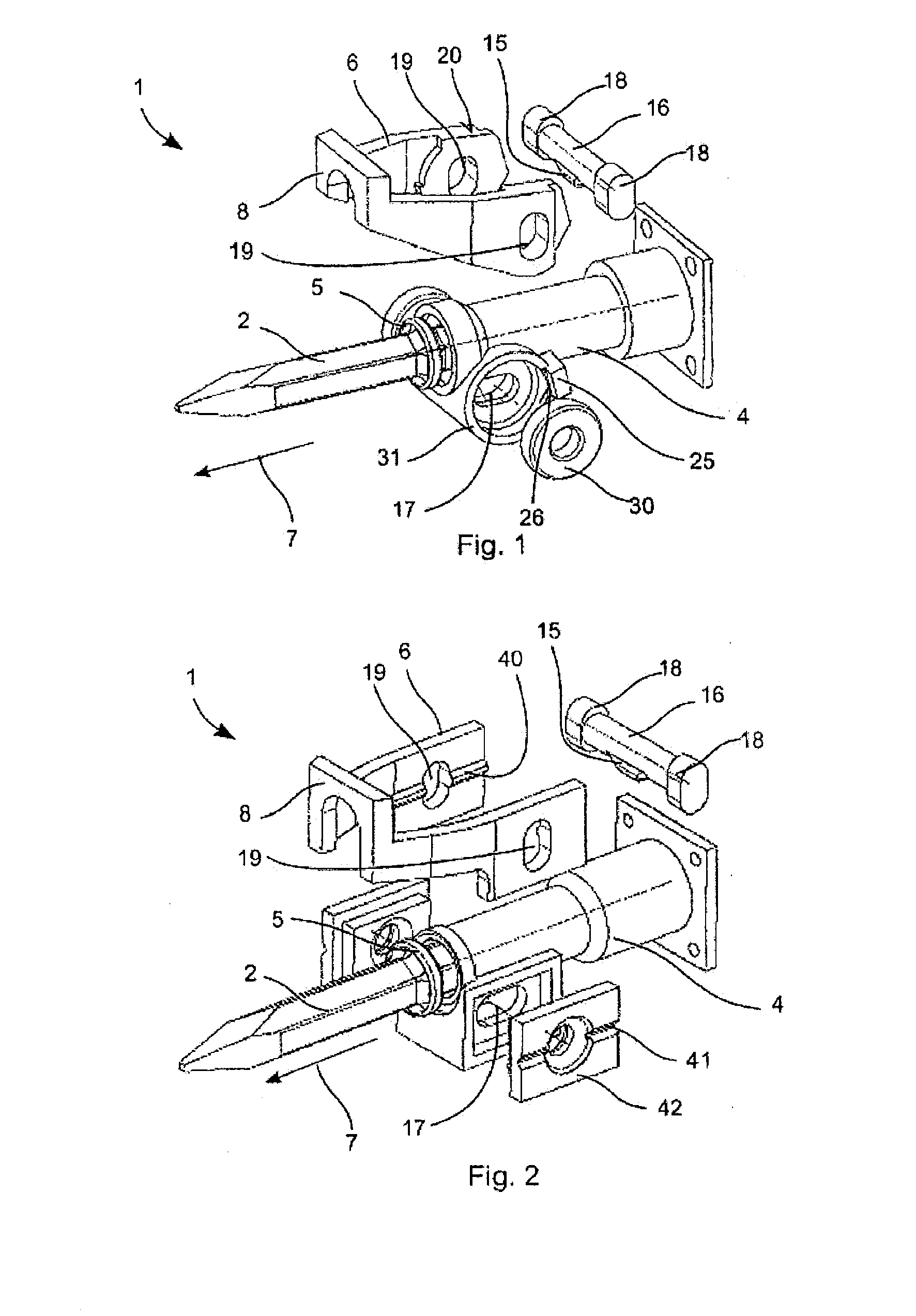
[0015]FIG. 1 shows an exploded view of an embodiment of a tool holder. The tool holder is constructed for holding tools 2, e.g., a chisel for a chipping hammer.

[0016]FIG. 2 shows an exploded view of another embodiment of a tool holder.

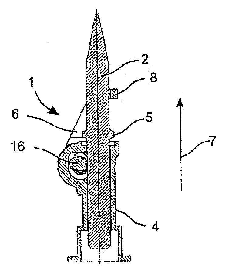
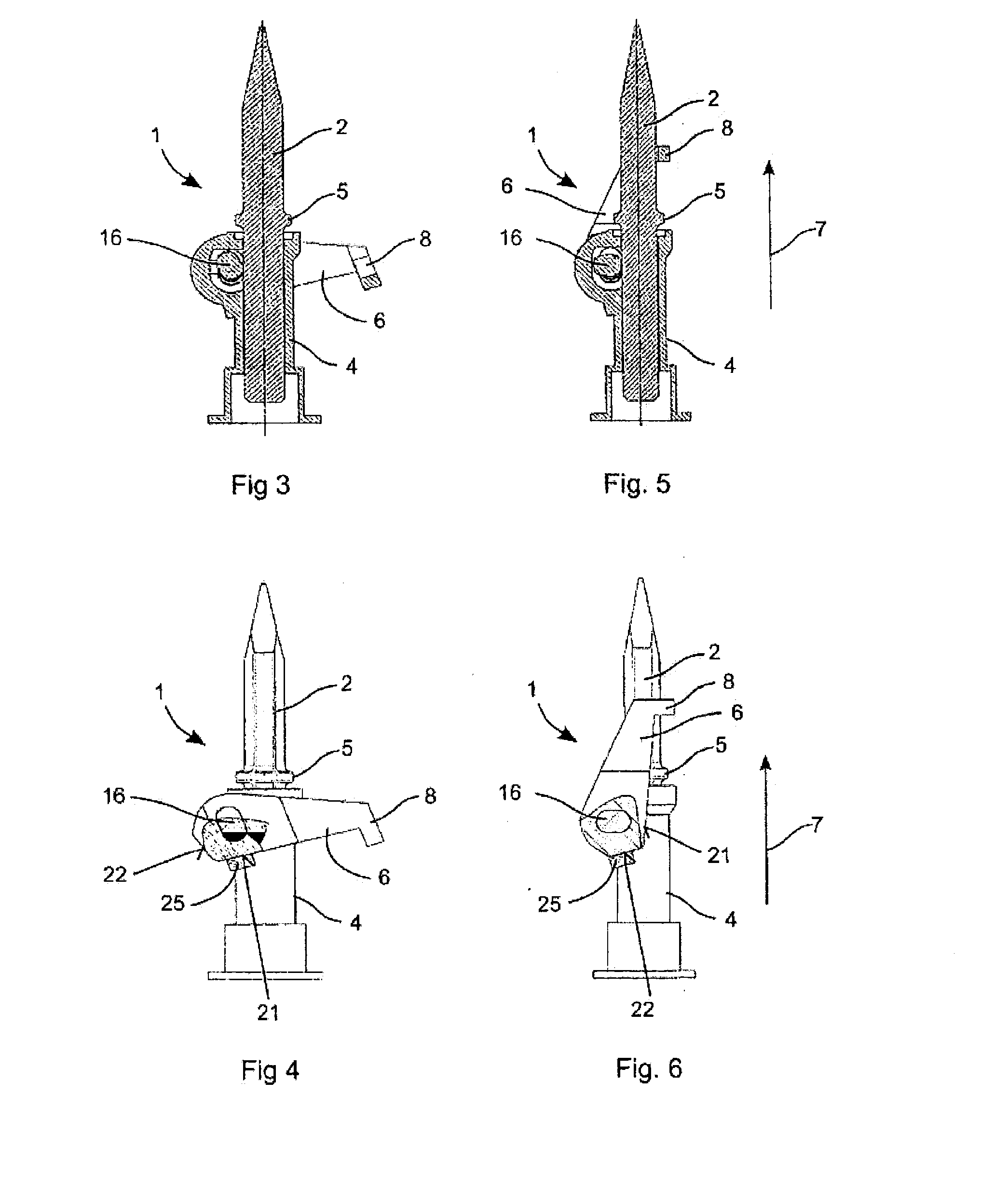
[0017]The longitudinal sections in FIGS. 3 to 6 depict a position for locking a tool of the first design in one of the tool holders and a position for inserting and removing the tool from the tool holder.

[0018]The longitudinal sections in FIGS. 7 to 10 show a position for locking a tool of the second design in one of the tool holders and a position for inserting and removing the tool from the tool holder.

[0019]The tool holders 1 are constructed for accommodating tools, in particular chisels. The known chisels 2 have two different designs with respect to how they are secured in a tool r...


PUM


Abstract

The tool holder according to the invention for a chipping hammer has a tool receptacle for receiving a tool and a tool securing device for securing the tool in the tool receptacle. The tool securing device provides a shaft having an eccentrically arranged mandrel and at least one end piece and a bar having at least one eye in which the end piece engages in a form-fitting manner. The tool securing device is pivotable into at least one first position for inserting and removing the tool and into at least one second position for securing the tool. The eye has a non-circular cross-section.

Description

FIELD OF THE INVENTION[0001]The present invention relates to a tool holder for a chipping hammer.DESCRIPTION OF THE PRIOR ART[0002]Tool holders with a lock for chipping hammers are known from EP 1 872 913 A2, among other places. The tool holder may accommodate two of the conventional designs for tools and secure the tools by setting a bar. Provision is also made for the bar to be locked in a position in which the tool may be inserted in the tool holder or may be removed from it.[0003]The bar is fastened on a rotatable shaft by means of pins. Strong forces act on the pins during the percussive operation of the chipping hammer. As a result, the pins are manufactured of highly resistant materials.DISCLOSURE OF THE INVENTION[0004]One object is making another tool holder available.[0005]The tool holder according to the invention for a chipping hammer has a tool receptacle for receiving a tool and a tool securing device for securing the tool in the tool receptacle. The tool securing devic...

Claims


Application Information

Patent Timeline
IPC IPC(8): B25D17/08
CPCB25D17/082B25D2250/211Y10T279/17051
Inventor KOCH, OLAFBUCHENAU, ALEXANDERHAMMERSTINGL, STEFANKEITH, MATTHIASPLANK, UTO
Owner HILTI AG
Why Eureka
Try Eureka