Linear voltage regulator and current sensing circuit thereof

a voltage regulator and current sensing technology, applied in the direction of electric variable regulation, process and machine control, instruments, etc., can solve the problems of resistance of the resistor rsub>z /sub>, unstable linear regulator,

Inactive Publication Date: 2012-02-16
NOVATEK MICROELECTRONICS CORP
View PDF7 Cites 68 Cited by
  • Summary
  • Abstract
  • Description
  • Claims
  • Application Information

AI Technical Summary

Benefits of technology

[0012]The invention is directed to a linear regulator and a current sensing circuit thereof, wherein the current sensing circuit correspondingly adjusts the variable resistor coupled to the compensation capacitor by sensing the pass current flowing through the pass transistor so as to achieve the pole-zero tracking effect.

Problems solved by technology

Thus, the phase margin will degrade, making the linear regulator unstable.
However, the above compensation technique still has a problem, that is, both the resistance of the resistor RZ and the transconductance of the transconductor gm of the pass transistor MNO vary with the manufacturing process.
However, as the transconductance gmMNO of the pass transistor MNO changes with the load current ILOAD, the frequency variation of the non-dominant pole may be large during the system operation.
The fixed zero frequency cannot be used effectively to cancel the non-dominant pole frequency at the output node VOUT, and the phase margin may still be insufficient under certain levels of load current ILOAD.

Method used


Image

  • Linear voltage regulator and current sensing circuit thereof
  • Linear voltage regulator and current sensing circuit thereof
  • Linear voltage regulator and current sensing circuit thereof

Examples


first embodiment

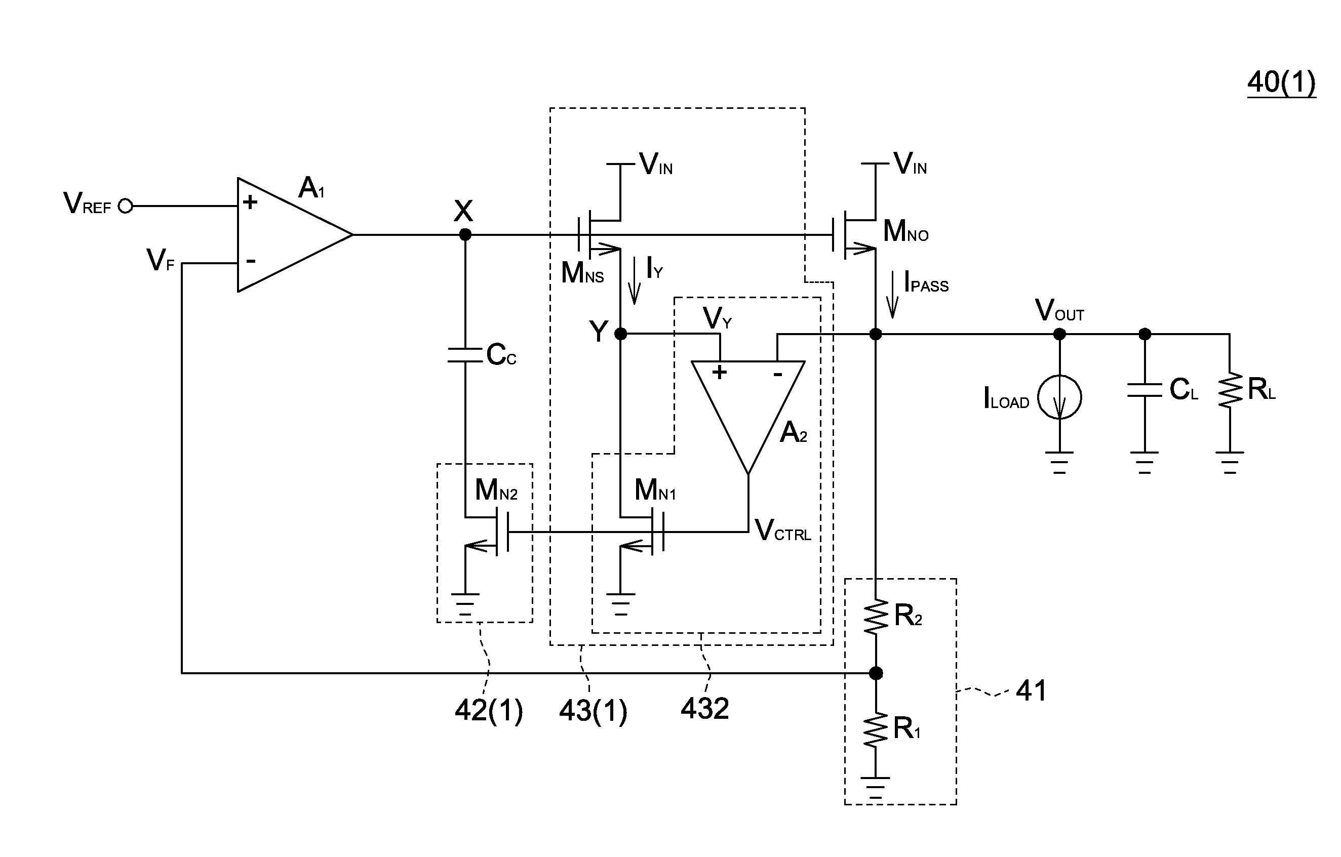
[0027]Referring to FIG. 4, an architect diagram of a linear regulator is shown. The linear regulator 40, realized by such as a high drop-out (HDO) linear regulator, comprises a pass transistor MNO, a compensation capacitor CC, a feedback network 41, an error amplifier A1, a variable resistor 42 and a current sensing circuit 43. For convenience of elaboration, the pass transistor MNO of FIG. 4 is exemplified by an N-type metal-oxide-semiconductor (MOS) transistor. However, the type of the pass transistor is not limited thereto, and the pass transistor can also be realized by a P-type MOS transistor, an NPN bipolar junction transistor (BJT) or a PNP bipolar junction transistor.

[0028]A first terminal of the pass transistor MNO receives an input voltage VIN, and a second terminal of the pass transistor MNO outputs an output voltage VOUT. A first terminal and a second terminal of the pass transistor MNO are realized by a drain and a source, respectively. The variable resistor 42 is coupl...

second embodiment

[0035]Referring to FIG. 6, a circuit diagram of a linear regulator of a second embodiment is shown. In the second embodiment, the linear regulator 40, the variable resistor 42 and the current sensing circuit 43 are exemplified by a linear regulator 40(2), a variable resistor 42(2) and a current sensing circuit 43(1), respectively. The second embodiment is different from the first embodiment mainly in the variable resistor 42(2), which further comprises a transistor MN3 in addition to the transistor MN2. A first terminal and a second terminal of the transistor MN3 are realized by such as a drain and a source, respectively. A control terminal of the transistor MN3 is realized by such as a gate. The first terminal of the transistor MN3 is coupled to a control terminal of the transistor MN3. The second terminal of the transistor MN3 is coupled to the compensation capacitor CC and the first terminal of the transistor MN2. The transistor MN3 operates in the saturation region to form an eq...

third embodiment

[0037]Referring to FIG. 7, a circuit diagram of a linear regulator of a third embodiment is shown. In the third embodiment, the linear regulator 40, the variable resistor 42 and the current sensing circuit 43 are exemplified by a linear regulator 40(3), a variable resistor 42(3) and a current sensing circuit 43(2), respectively. The third embodiment is different from the second embodiment mainly in the variable resistor 42(3) and the current sensing circuit 43(2). The current sensing circuit 43(2) further comprises a transistor MN2, which is coupled between the variable resistor 42(3) and the ground terminal. The control terminal of the transistor MN2 is coupled to the output terminal of the sense amplifier A2. The transistor MN2 is controlled by the sense amplifier A2. The variable resistor 42(3) merely comprises a transistor MN3. A first terminal and a second terminal of the transistor MN3 are realized by such as a drain and a source, respectively. A control terminal of the transi...


PUM


Abstract

A linear regulator and a current sensing circuit are provided. The linear regulator comprises a pass transistor, a compensation capacitor, a variable resistor, an error amplifier and a current sensing circuit comprising a sense transistor controlled by the error amplifier and a voltage follower coupled with the second terminal of the pass transistor and the second terminal of the sense transistor. The sense transistor receives an input voltage, and generates a sense current proportional to a pass current. The voltage follower controls the voltage at the second terminal of the sense transistor to be the same as that at the second terminal of the pass transistor, and adjusts the resistance of the variable resistor according to the voltages at the second terminal of the pass transistor, the voltage at the second terminal of the sense transistor, and the sense current flowing through the sense transistor.

Description

[0001]This application claims the benefit of Taiwan application Serial No. 99126663, filed Aug. 10, 2010, the subject matter of which is incorporated herein by reference.BACKGROUND OF THE INVENTION[0002]1. Field of the Invention[0003]The invention relates in general to a linear regulator and a current sensing circuit thereof, and more particularly to a linear regulator with pole-zero tracking function and a current sensing circuit thereof.[0004]2. Description of the Related Art[0005]Referring to FIG. 1, a circuit diagram of a first conventional linear regulator is shown. The conventional linear regulator 10 comprises a pass transistor MNO, a compensation capacitor CC, a feedback network 41 and an amplifier A1. The first terminal of the pass transistor MNO receives an input voltage VIN, and the second terminal of the pass transistor MNO outputs the output voltage VOUT to a load. A first terminal and a second terminal of the pass transistor MNO are realized by such as a drain and a so...

Claims


Application Information

Patent Timeline
Patent Type & Authority Applications(United States)
IPC IPC(8): G05F1/573
CPCG05F1/575
Inventor LIN, YUNG-CHENG
Owner NOVATEK MICROELECTRONICS CORP
Why Eureka
Try Eureka