Expanded Heat Sink for Electronic Displays and Method of Producing the Same

a technology of electronic displays and heat sinks, which is applied in the direction of lighting and heating apparatus, instruments, laminated elements, etc., can solve the problems of a significant source of heat, a relatively large amount of power required by illumination devices, and a limited number of heat sinks

Inactive Publication Date: 2012-02-16
MFG RESOURCES INT INC
View PDF4 Cites 56 Cited by
  • Summary
  • Abstract
  • Description
  • Claims
  • Application Information

AI Technical Summary

Benefits of technology

[0008]In one embodiment where the electronic display is a liquid crystal display, power modules and the display backlight may be placed in thermal communication with the continuous conductive sheet. In this way, a single path of cooling air can be used to cool two of the most heat-producing components of a typical LCD. For example, and not by way of limitation, LED arrays are commonly used as the illumination devices for LCD backlights. It has been found that the optical properties of LEDs (and other illumination devices) can vary depending on temperature. Thus, when an LED is exposed to room temperatures, it may output light with a certain luminance, wavelength, and / or color temperature. However, when the same LED is exposed to high temperatures, the luminance, wavelength, color temperature, and other properties can vary. Thus, when a temperature variation occurs across an LED backlight (some areas are at a higher temperature than others) there can be optical inconsistencies across the backlight which can be visible to the observer. By using the exemplary embodiments herein, heat buildup can be evenly distributed across the continuous conductive sheet and removed from the display. This can prevent any potential ‘hot spots’ in the backlight which may become visible to the observer because of a change in optical properties of the LEDs.
[0009]The continuous conductive sheet may provide an isolated chamber from the rest of the display so that ambient air can be ingested and used to cool the continuous conductive sheet. This is beneficial for situations where the display is being used in an outdoor environment and the ingested air may contain contaminates (pollen, dirt, dust, water, smoke, etc.) that would damage the sensitive electronic components of the display.

Problems solved by technology

These heat sinks have previously been limited to only the size of the power module itself.
Further, the illumination devices require a relatively large amount of power in order to generate the required brightness level.
These power supplies may also become a significant source of heat for the display.
When surrounding temperatures rise, the cooling of the internal display components can become even more difficult.
Still further, in some situations radiative heat transfer from the sun through the front portion of the display can also become a source of heat.
Furthermore, the market is demanding larger screen sizes for displays.

Method used


Image

  • Expanded Heat Sink for Electronic Displays and Method of Producing the Same
  • Expanded Heat Sink for Electronic Displays and Method of Producing the Same
  • Expanded Heat Sink for Electronic Displays and Method of Producing the Same

Examples


Embodiment Construction

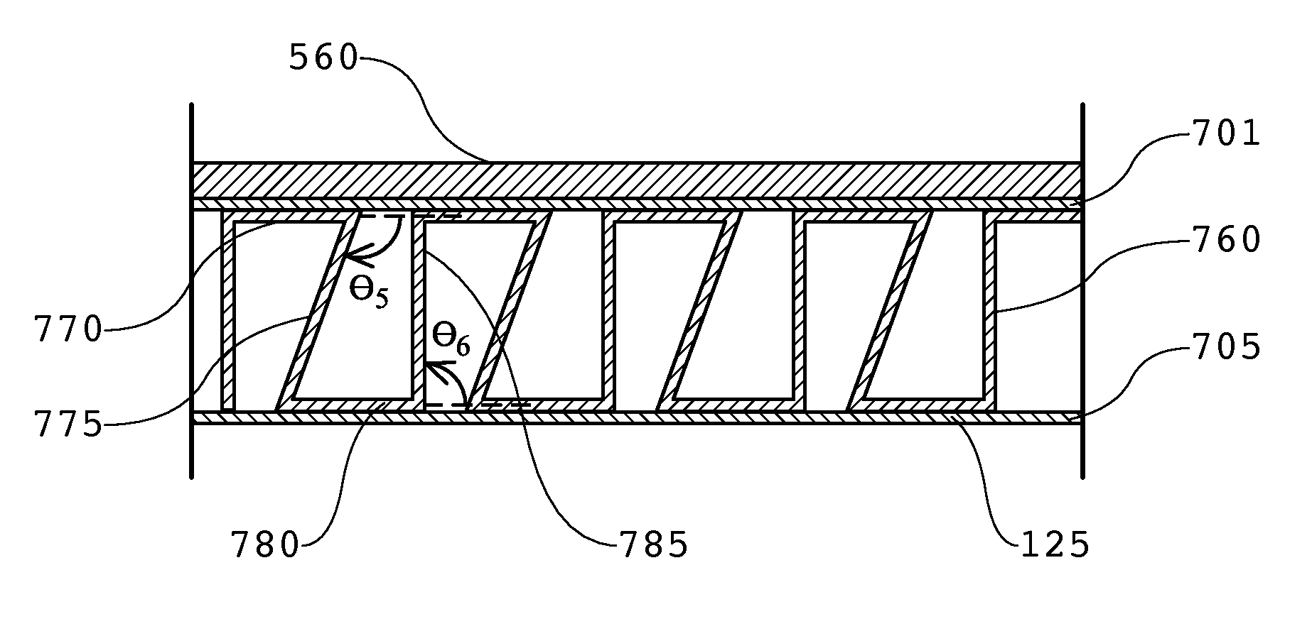
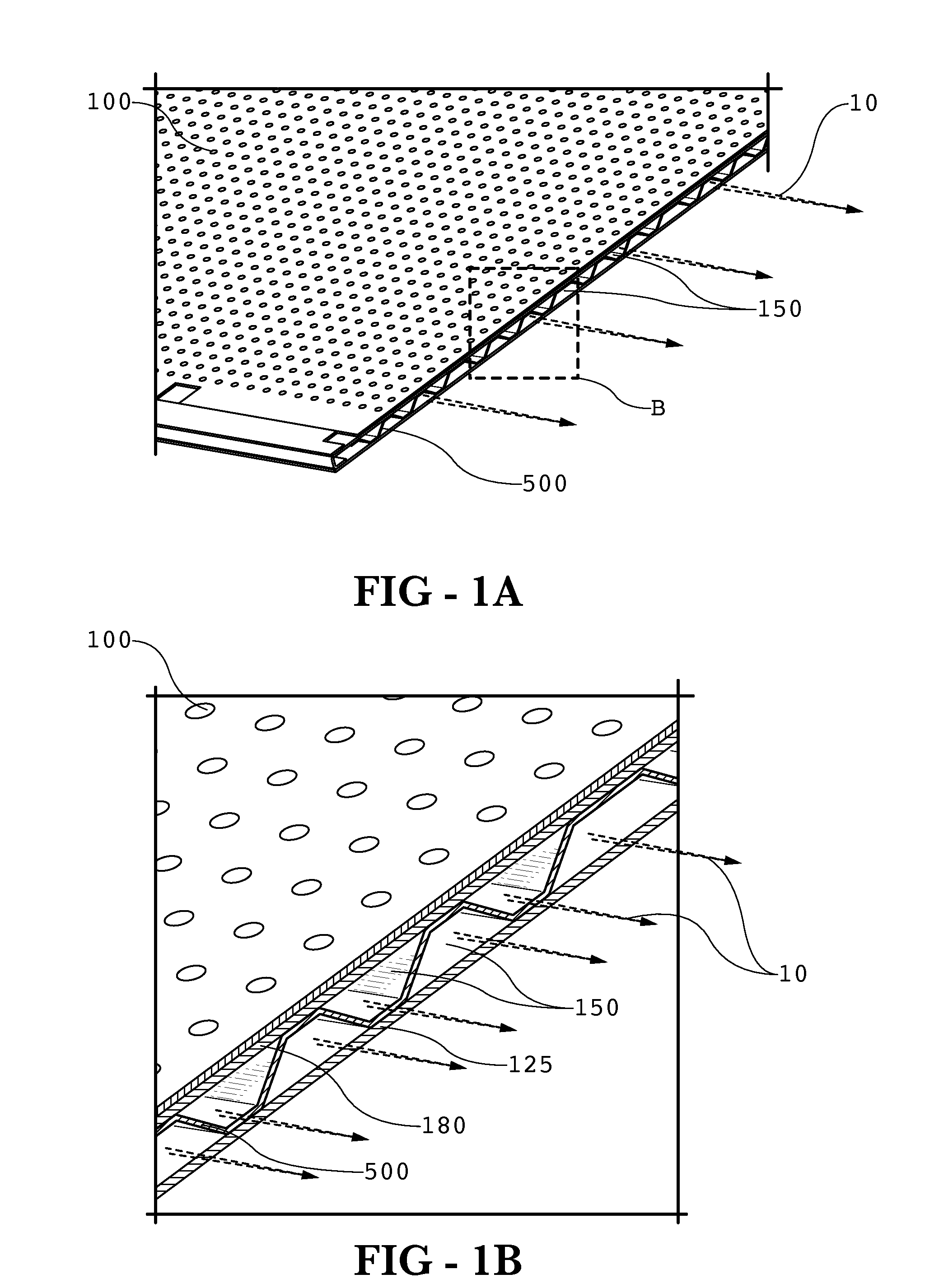
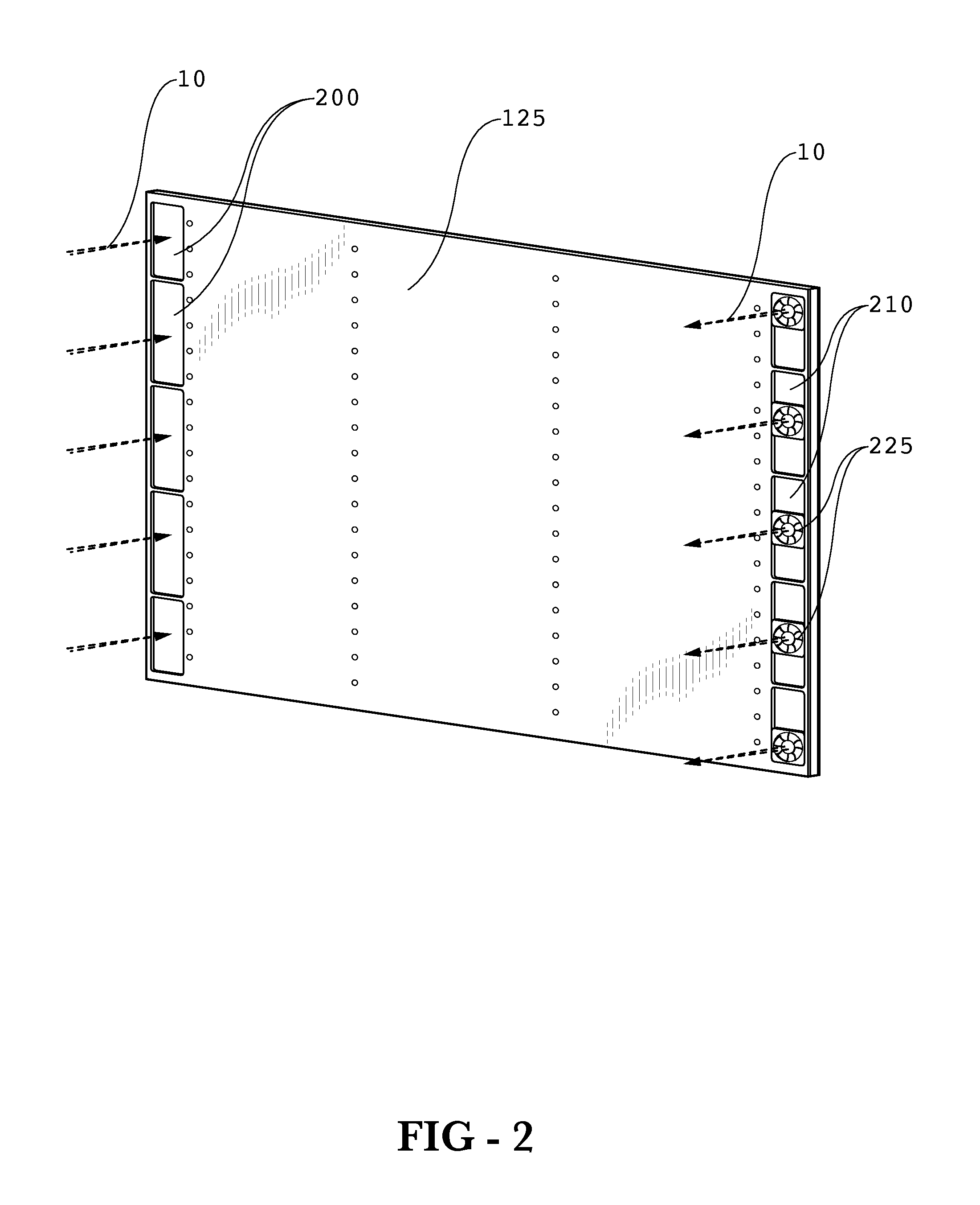
[0007]Exemplary embodiments relate to a system for cooling various components of an electronic display. The exemplary embodiments may be used to cool the power module(s) or power transformer(s), backlight (if used in the particular display), and other internal components of an electronic display, either alone or in combination. The component(s) may be placed in thermal communication with a continuous conductive sheet which may be placed in the path of cooling air. The heat from the components are distributed throughout the continuous conductive sheet and removed by the cooling air. Some embodiments may place the continuous conductive sheet between a pair of substantially parallel plates (which may also be conductive and may be in thermal communication with the continuous conductive sheet and one or more components).

[0008]In one embodiment where the electronic display is a liquid crystal display, power modules and the display backlight may be placed in thermal communication with the ...


PUM

PropertyMeasurementUnit
anglesaaaaaaaaaa
angles θ3aaaaaaaaaa
conductiveaaaaaaaaaa

Abstract

An expanded heat sink for transferring heat from an electronic display component to a path of cooling air is disclosed. A continuous sheet may define a series of channels where the cooling air is blown through the channels and along the continuous sheet. When viewed along the path of the cooling air and oriented horizontally, the continuous sheet may define a series of four-sided polygons having top, bottom, left side, and right side portions where either the top or bottom portions are absent from each polygon. The absent top portions may be supplied by a front plate or the rear portion of an electronic display. The absent bottom portions maybe supplied by a rear plate. One or more components of the electronic display may be placed in thermal communication with the sheet and/or front/rear plates to transfer heat from the components to the cooling air.

Description

CROSS-REFERENCE TO RELATED APPLICATIONS[0001]This application claims priority to U.S. Application No. 61 / 372,942, filed on Aug. 12, 2010, herein incorporated by reference in its entirety.TECHNICAL FIELD[0002]Exemplary embodiments generally relate to cooling systems and in particular to cooling systems for electronic displays.BACKGROUND OF THE ART[0003]Conductive and convective heat transfer systems for electronic displays generally attempt to remove heat from the electronic components in a display through the sidewalls of the display. Components such as power modules, which are known for producing a large amount of heat may have a ‘heat sink’ attached to the component which provides an expanded surface area so that heat may be transferred away from the component. These heat sinks have previously been limited to only the size of the power module itself.[0004]Modern displays have become extremely bright, with some LCD backlights producing 1,000-2,000 nits or more. Sometimes, these ill...

Claims


Application Information

Patent Timeline
Patent Type & Authority Applications(United States)
IPC IPC(8): G02F1/13357F28F7/00H05K7/20
CPCF28D1/0366F28F3/025H05K7/20972F21V29/00G02F1/1333H05K7/20
Inventor DUNN, WILLIAMHUBBARD, TIM
Owner MFG RESOURCES INT INC
Why Eureka
Try Eureka