

Communication network control system and control method
- Summary
- Abstract
- Description
- Claims
- Application Information
AI Technical Summary
Benefits of technology
Problems solved by technology
Method used
Image

Examples
example 1
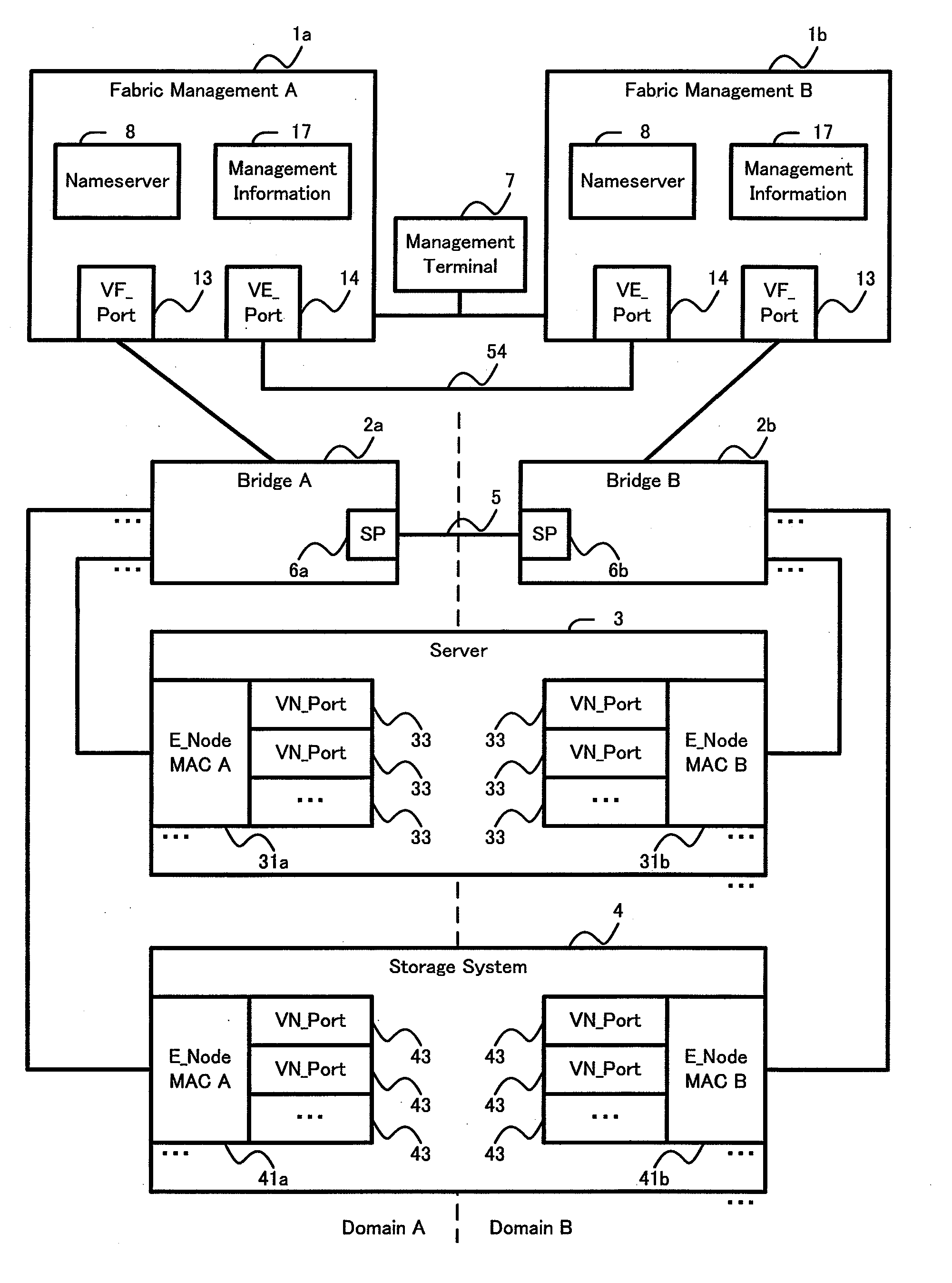
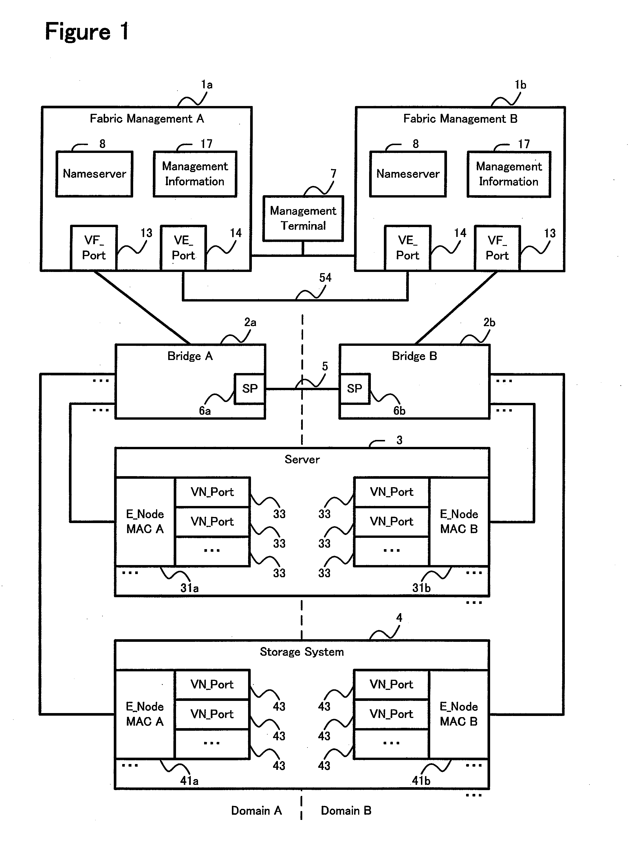
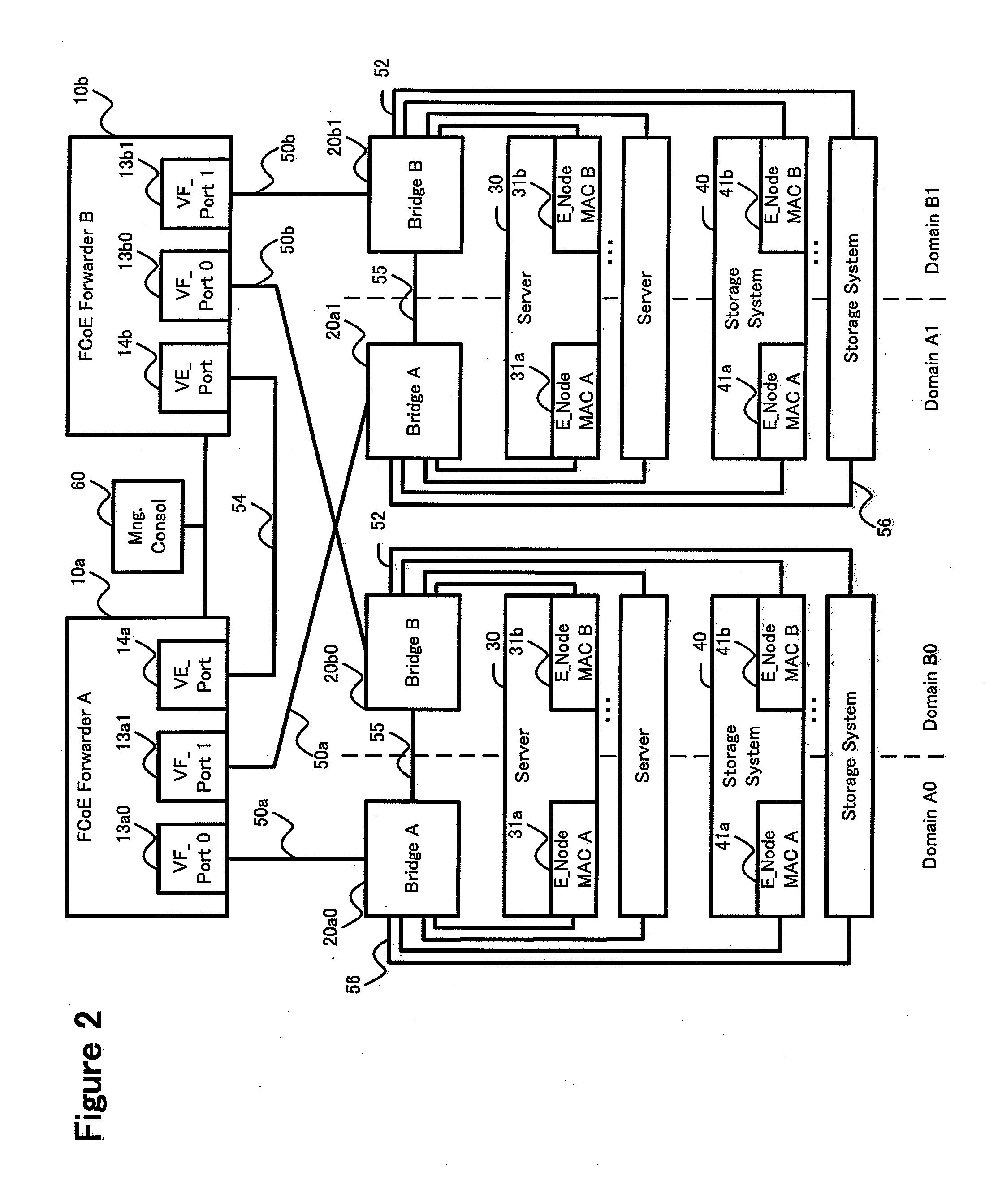
[0075]FIG. 2 shows a communication network control system of this example. The system shown in FIG. 2 is redundantly configured using a domain A, which is managed by the FCoE Forwarder (FCF) 10a, and a domain B, which is managed by the FCoE Forwarder 10b. The FCF is a device that comprises a FC switching mechanism, a mechanism for managing the FC fabric, and control information. This FCF may also be a device that comprises a mechanism for managing the FC fabric and control information without having the FC switching mechanism as in FIG. 1.
[0076]Two arrays of computer apparatuses are provided. The computer apparatuses in this explanation signify either the server or the storage system. Each computer apparatus comprises separate E_Node MACs 31a and 31b that belong respectively to system A (called Domain A) and system B (called Domain B).
[0077]FCF 10a VF_Ports 13a0 and 13a1 are coupled to bridges 20a by way of physical links 50a. The bridge 20a is coupled to E_Node MACs 31a and 41a of ...
example 2
[0137]A second example will be explained by referring to FIGS. 13 and 14. Each of the following examples, to include this example, corresponds to a variation of the first example. Therefore, the explanations will focus on those points that differ from the first example. In this example, the FCFs 10a and 10b are redundantly coupled to one another's fabric.
[0138]FIG. 13 shows the essential elements of a network system according to this example. The bridge 20a is coupled to the VF_Port 13A of the FCF 10b of the domain 13 by way of a physical link 70. Similarly, the bridge 20b is coupled to the VF_Port 13B of the FCF 10a of the other domain by way of another physical link 71. Focusing on the bridges 20a, 20b, the bridge 20a is coupled to the VF_Port 13A of the FCF 10a and the VF_Port 13A of the FCF 10b, and the bridge 20b is coupled to the VF_Port 13B of the FCF 10a and the VF_Port 13B of the FCF 10b.
[0139]The physical links 70 and 71 are stand-by link in a case where the communication...
example 3
[0141]A third example will be explained by referring to FIGS. 15 and 16. In this example, a physical link 55a, which couples the bridges 20a and 20b, is also used in a case where the communication network is normal. FIG. 15 shows a system in a case where the communication network is normal, and FIG. 16 is a diagram showing a post-failover system.
[0142]The FCFs 10a and 10b use an inter-bridge physical link 55a to provide communication path P30. The FCFs 10a and 10b exchange management information with each other via the communication path P30 that uses a logical link of the physical link 55a. However, the logical link from the domain A to the domain B and the logical link from the domain B to the domain A are both state of stand-by logical link at normal times. That is, when the system is operating normally, the physical link 55a is used for exchanging management information. The physical link 55a, for example, is logically partitioned into a management information communication path...
PUM
 Abstract
Description
Claims
Application Information