
Endoscopic system for enhanced visualization

Active Publication Date: 2012-02-16
BOSTON SCI SCIMED INC
View PDF34 Cites 89 Cited by
  • Summary
  • Abstract
  • Description
  • Claims
  • Application Information

AI Technical Summary

Benefits of technology

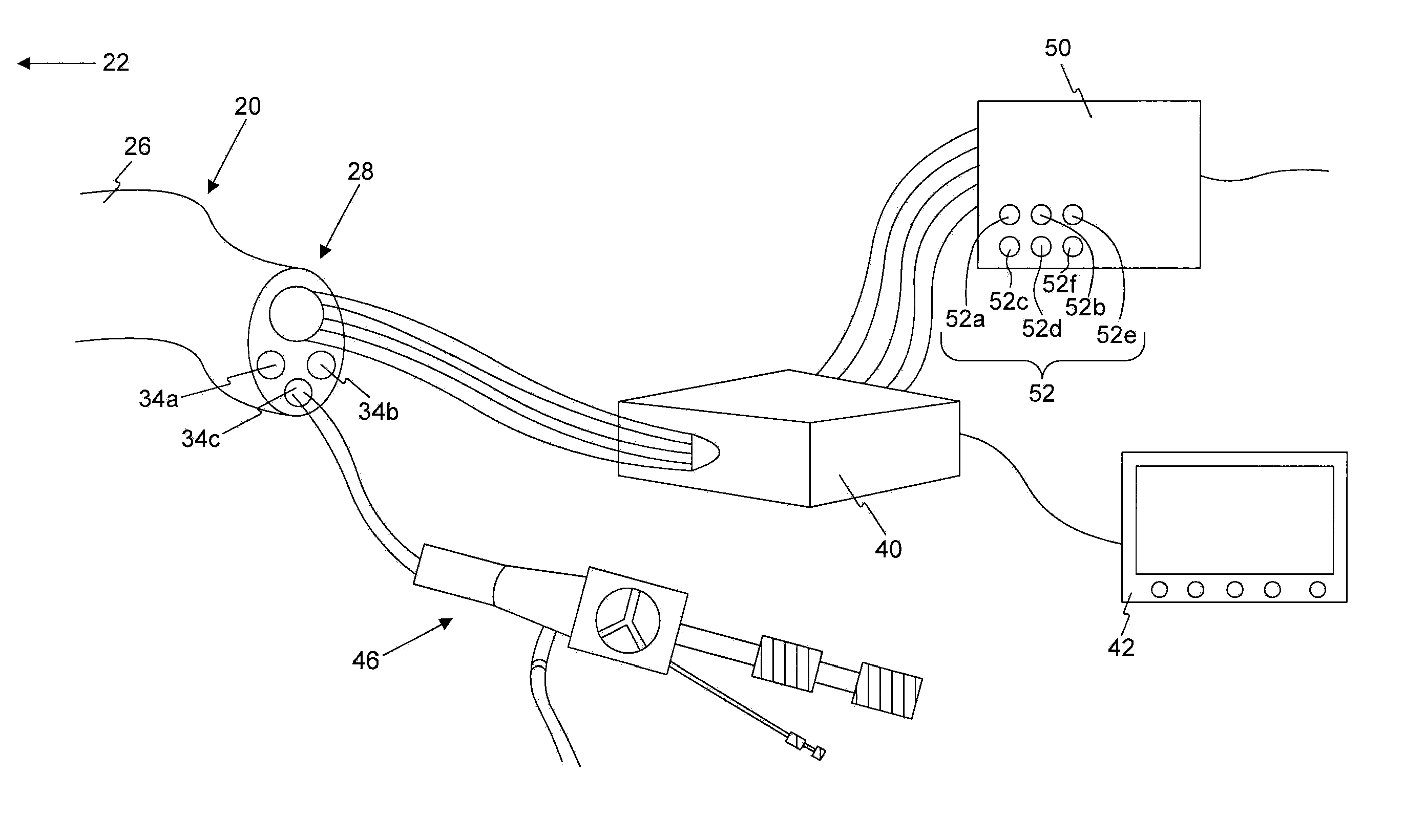
[0009]Various embodiments of the invention may include one or more of the following aspects: adjusting the characteristic of light may include varying an intensity of light directed through one of the light sources independent of the intensity of light directed through the other of the light sources; adjusting the characteristic of light may include manually adjusting the characteristic of light directed through one of the light sources independent of the characteristic of light directed through the other of the light sources; adjusting the characteristic of light may include automatically adjusting the characteristic of light directed through one of the light sources independent of the characteristic of light directed through the other of the light sources based on an illumination of the received image; and the characteristic of light may include at least one of an intensity, a wavelength, a polarization, a frequency, or a phase of light.
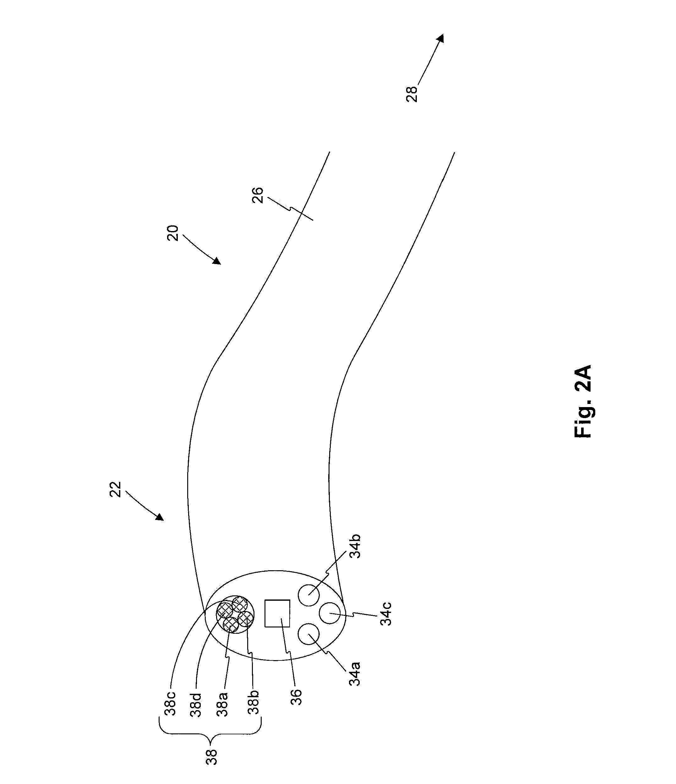
[0010]An embodiment of the invention may further include an endoscope. The endoscope may include an elongate body extending from a proximal end to a distal end, and an imaging device positioned at the distal end. The imaging device may be configured to direct an image of a work site proximate the distal end to a viewing device positioned proximate the proximal end. The endoscope may also include a plurality of light sources positioned at the distal end. The plurality of

Problems solved by technology

For instance, some of these locations may appear to be oversaturated with light while other locations may appear to be insufficiently illuminated.
This variation in illumination may make visualization of the work site difficult, and may therefore be undesirable.
An endoscope with a diffusing lens may, however, be limited to providing uniform light across the entire field of view.
Additionally, with small bore endoscopes, the cost of implementing a diffusing lens for even distribution of light may be high.
While this cost may be less of an issue with reusable endoscopes where the cost can be amortized due to repeated usage, this cost may be prohibitively high in the case of disposable endoscopes.

Method used


Image

  • Endoscopic system for enhanced visualization
  • Endoscopic system for enhanced visualization
  • Endoscopic system for enhanced visualization

Examples


Embodiment Construction

[0018]Reference will now be made to exemplary embodiments of the invention, examples of which are illustrated in the accompanying drawings. Wherever possible, the same reference numbers will be used throughout the drawings to refer to the same or like parts.

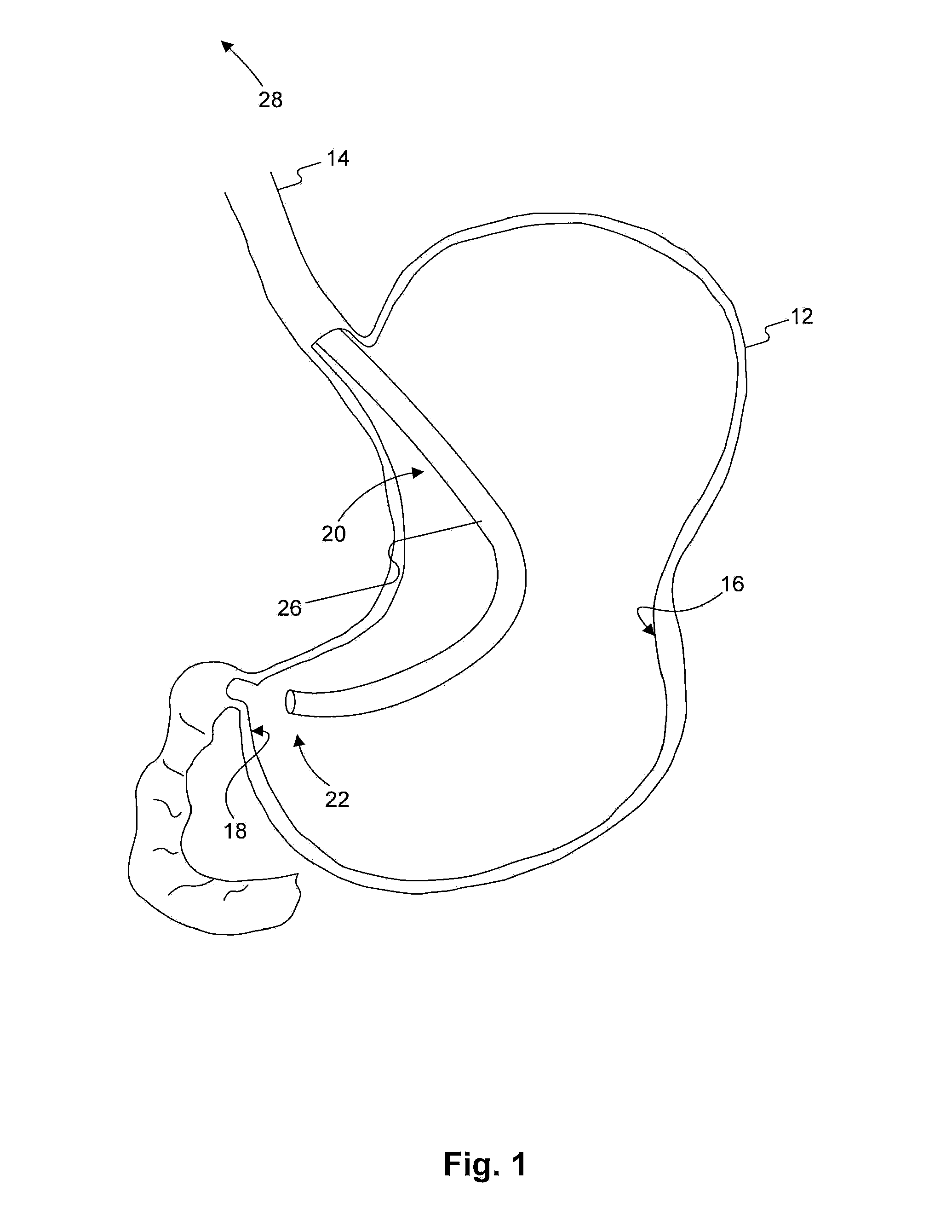
[0019]The terms “proximal” and “distal” are used herein to refer to the relative positions of the exemplary endoscopic device 20. When used herein, “proximal” refers to a position relatively closer to the exterior of the body or closer to the surgeon using the endoscopic device 20. In contrast, “distal” refers to a position relatively further away from the surgeon using the endoscopic device 20 or closer to the interior of the body.

[0020]FIG. 1 depicts an exemplary endoscopic device 20 performing an exemplary medical procedure on a patient. Endoscopic device 20 may be inserted into stomach 12 through the esophagus 14, and positioned in stomach 12 such that a distal end 22 of endoscopic device 20 may be positioned proximate a work...


PUM


Abstract

A medical device, configured for insertion into a body, may include an elongate member extending from a proximal end to a distal end, where the distal end may be configured to be positioned inside the body. The medical device may also include an imaging device positioned at the distal end. The medical device may further include a plurality of light sources positioned at the distal end, wherein a characteristic of light delivered through a first light source may be controlled independent of the characteristic of light delivered through a second light source.

Description

CROSS-REFERENCE TO RELATED APPLICATIONS [0001]This application is based upon and claims the benefit of priority under 35 U.S.C. §119(e) of U.S. Provisional Application No. 61 / 372,114 to Benning et al. filed on Aug. 10, 2010.FIELD OF THE INVENTION [0002]Embodiments of the present invention relate to an endoscopic system. In particular, exemplary embodiments of the present invention relate to endoscopes for enhanced visualization. Embodiments of the present invention also cover methods of using such devices.BACKGROUND OF THE INVENTION[0003]An endoscope is a flexible instrument introduced into the body for diagnostic or therapeutic purposes. Typically, these devices are inserted into the body through an opening (a natural opening or an incision), and are delivered to a work site inside the body through a body channel, such as, for example, the esophagus. Imaging devices incorporated in the endoscope allows a surgeon to see the work site from outside the body and remotely operate the en...

Claims


Application Information

Patent Timeline
IPC IPC(8): A61B1/06
CPCA61B1/0607A61B1/0638A61B1/07A61B1/0684A61B1/0676A61B1/0655
Inventor BENNING, CHRISTOPHERAQUILINO, PAUL
Owner BOSTON SCI SCIMED INC
Learn More