Adhesive wafer for use in a collecting device

a collection device and adhesive wafer technology, applied in the field of radially divided adhesive wafers, can solve the problems of wear of the adhesive wafer, cracks between the adhesive and the substrate that propagate through the interface, and difficulty in getting, so as to improve the control of the distribution of pulling force, increase the time before a leakage may occur, and prevent leakage.

Active Publication Date: 2012-02-16
COLOPLAST AS
View PDF4 Cites 17 Cited by
  • Summary
  • Abstract
  • Description
  • Claims
  • Application Information

AI Technical Summary

Benefits of technology

[0014]By providing an adhesive wafer as described, it has been shown that the time before a leakage occurs may be increased. In many cases, the leakage is even prevented. This results in the user being able to wear the adhesive wafer for a longer period of time.
[0015]The features described allows for a better control of the distribution of pulling forces which occur in particular as the collecting bag fills up. The control is particularly improved in cases where a crack has propagated between the skin and the inner annular adhesive layer, i.e. the annular adhesive layer closest to the body opening.

Problems solved by technology

This results in the user being able to wear the adhesive wafer for a longer period of time.
In this way, you initiate a crack between the tape and substrate that propagates through the interface when you peel it off.
You would not start to remove it from the center of the tape because (besides the fact that it would be difficult to get hold of) the forces needed to remove the tape would be much higher than if you try to peel it from the ends.

Method used


Image

  • Adhesive wafer for use in a collecting device
  • Adhesive wafer for use in a collecting device
  • Adhesive wafer for use in a collecting device

Examples


Embodiment Construction

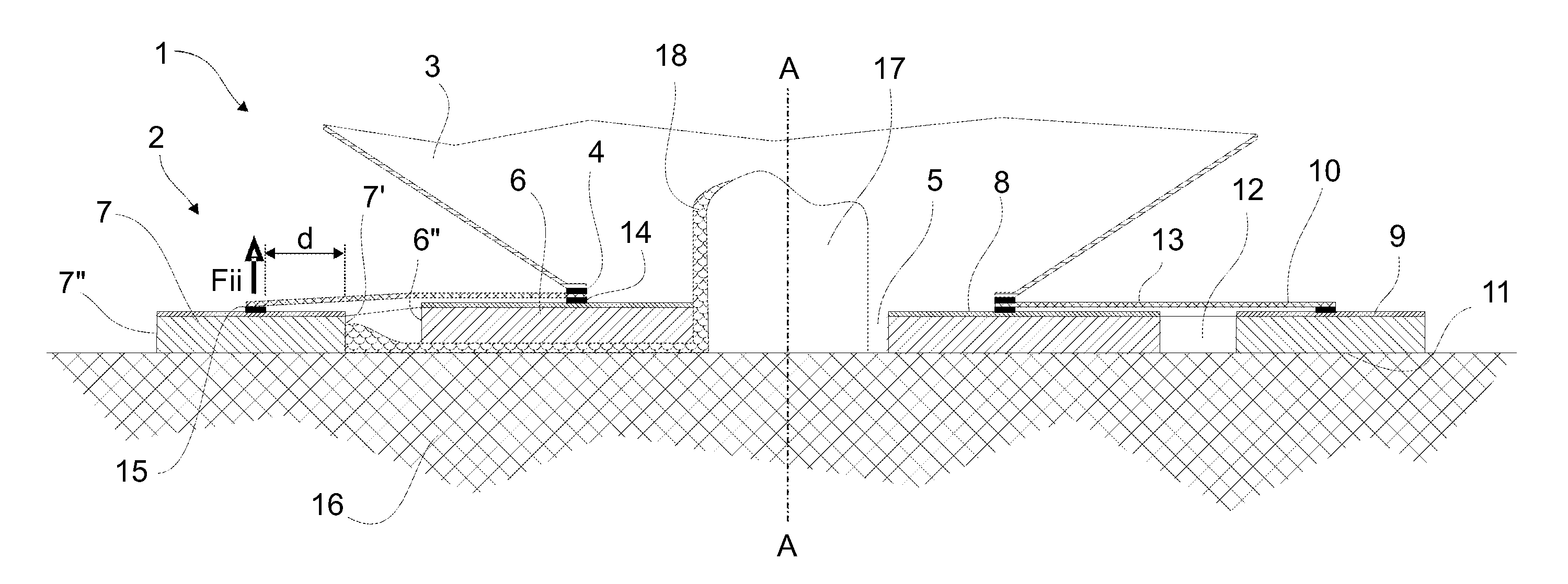
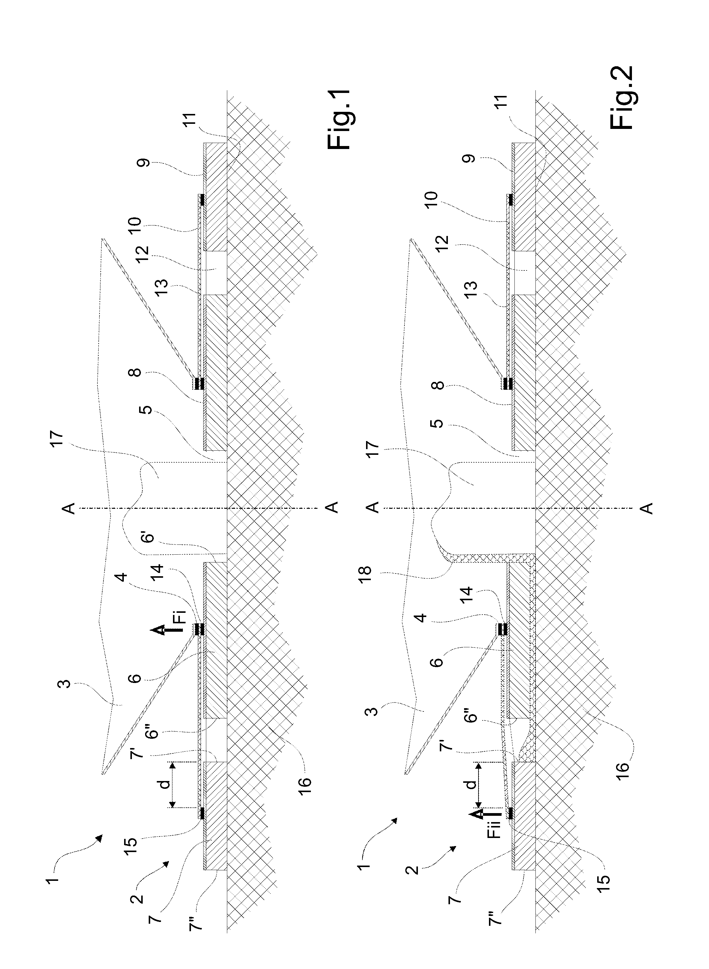
[0042]A first embodiment of an ostomy appliance 1 is shown in section in FIG. 1 and 2.

[0043]The ostomy appliance 1 is formed of an adhesive wafer 2, to which an ostomy bag 3 is attached by a first annular weld 4.

[0044]A through-going hole 5 extends longitudinally along axis A-A through the adhesive wafer 2. As can be seen, the ostomy bag 3 is attached around the through-going hole 5 in order to allow material entering the through-going hole to be collected in the ostomy bag.

[0045]The adhesive wafer 2 is formed of a first annular adhesive layer 6 and a second annular adhesive layer 7. The first and second annular adhesive layers 6,7 extend radially (i.e. perpendicularly to the longitudinal axis A-A of the through-going hole) between a first and a second inner radial edge 6′,7′ and a first and a second outer radial edge 6″,7″ which define the radial extent of the respective annular adhesive layers.

[0046]As can be seen, the first outer radial edge 6″ has a smaller radius from the axis ...


PUM


Abstract

The current invention relates to radially divided adhesive wafers for applying to the skin of a human, and which increases the wear time of such adhesive wafers. More specifically, detailed embodiments relating to radially divided adhesive wafers for use in ostomy appliances are described. This is done by providing an adhesive wafer comprising a through-going hole for communication with a body opening and an adhesive proximal side for attachment of the wafer to the skin surrounding the body opening. The adhesive wafer comprises an inner annular adhesive layer, an outer annular adhesive layer encircling the inner annular adhesive layer, an attachment zone for attaching a collection bag, provided on the distal side of the adhesive wafer, and connection means for mechanically connecting the first annular adhesive layer to the second annular adhesive layer, wherein the connection means comprises a first and a second connection area on the distal side of the respective first and second annular adhesive layers, wherein at least one of the connection areas are arranged in a radial distance from the radial edges of the respective annular adhesive layer. By providing an adhesive wafer as described, it has been shown that the time before a leakage occurs may be increased. In many cases, the leakage is even prevented. This results in the user being able to wear the adhesive wafer for a longer period of time.

Description

TECHNICAL FIELD[0001]The current invention relates to radially divided adhesive wafers for applying to the skin of a human, and which increases the wear time of such adhesive wafers.[0002]More specifically, detailed embodiments relating to radially divided adhesive wafers for use in ostomy appliances are described.BACKGROUND[0003]A major concern for users of collecting devices, such as ostomy devices for collecting fecal output from the stoma, is the occurrence of leakage during wear. Herein, a leakage or leak is understood as being output from a stoma, or other body opening, that works its way in between the skin and the adhesive interface of the ostomy device, all the way from the stoma to the outer periphery of the adhesive wafer. Apart from being unhealthy to the skin that gets in contact with the stoma output, the leak often results in discomfort and potential embarrassing situations for the user.[0004]One way of reducing the risk of leakage is by dividing the adhesive wafer, w...

Claims


Application Information

Patent Timeline
Patent Type & Authority Applications(United States)
IPC IPC(8): A61F5/449
CPCA61F5/443
Inventor BACH, ANDERSCIOK, DANUTASTROEBECH, ESBEN
Owner COLOPLAST AS
Why Eureka
Try Eureka