
Dual-mode illumination for surgical instrument

a surgical instrument and dual-mode technology, applied in the field of optical fiber array configuration, can solve the problems of reducing the clinical value of the surgical instrument, causing retinal tear or hole, and shrinking the vitreous body

Active Publication Date: 2012-02-16
ALCON INC
View PDF8 Cites 34 Cited by
  • Summary
  • Abstract
  • Description
  • Claims
  • Application Information

AI Technical Summary

Problems solved by technology

Syneresis results in shrinkage of the vitreous body, which can exert pressure or traction on its normal attachment sites.
If enough traction is applied, the vitreous body may pull itself from its retinal attachment and create a retinal tear or hole.
These efforts have been difficult because of the small diameters of vitrectomy probes.
Known illumination devices, such as those described above, can provide end illumination, though with deficiencies as noted, but there are no available devices that combine end and side illumination, and the ability to provide one or the other or both, in a small diameter instrument.
The same constraints described above also restrict the feasible size of other ophthalmic surgical instruments.

Method used


Image

  • Dual-mode illumination for surgical instrument
  • Dual-mode illumination for surgical instrument
  • Dual-mode illumination for surgical instrument

Examples


Embodiment Construction

[0028]Reference is now made in detail to the exemplary embodiments of the invention, examples of which are illustrated in the accompanying drawings. Wherever possible, the same reference numbers are used throughout the drawings to refer to the same or like parts.

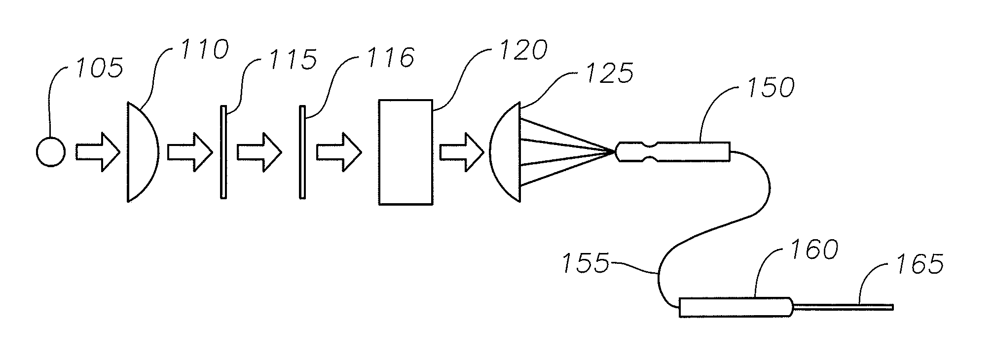
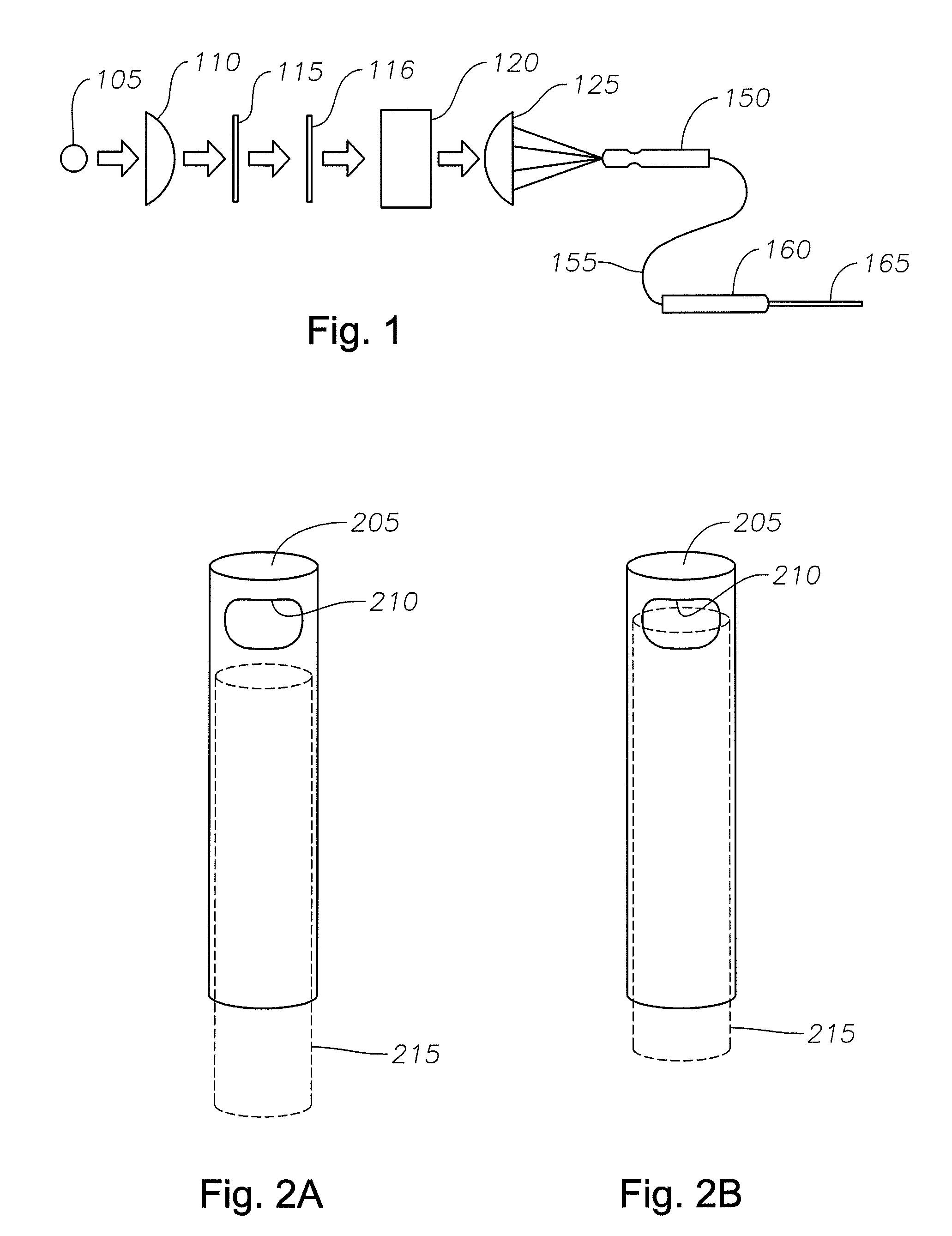
[0029]FIG. 1 is an unfolded view of an exemplary ophthalmic endoilluminator as used with an illuminated vitrectomy probe according to an embodiment of the present invention. In FIG. 1, the endoilluminator includes light source 105, collimating lens 110, optional cold mirror 115, optional hot mirror 116, attenuator 120, condensing lens 125, connector 150, optical fiber 155, hand piece 160, and vitrectomy probe 165.

[0030]The light from light source 105 is collimated by collimating lens 110. The collimated light is reflected and filtered by optional cold mirror 115 and / or transmitted and filtered by optional hot mirror 116. The resulting beam is attenuated by attenuator 120 and focused by condensing lens 125. The focused beam i...


PUM


Abstract

An illuminated surgical instrument is disclosed. One embodiment of the present invention comprises an illuminated vitrectomy probe. The vitrectomy probe has a cutting port disposed at a distal end of a cannula. An array of optical fibers terminates near the cutting port. The array of optical fibers is located adjacent to the cannula and encircling the cannula. The array of optical fibers can comprise two sets of fibers, one for providing illumination in a direction along a longitudinal axis of the vitrectomy probe and another for providing illumination in a direction at an angle to the longitudinal direction of the vitrectomy probe. The light source providing light to each set of fibers can be independently controlled so as to provide illumination cooperatively or singly.

Description

[0001]This application claims priority to U.S. Provisional Patent Application Ser. No. 61 / 373,575 filed on Aug. 13, 2010, the entire contents of which are incorporated herein.BACKGROUND OF THE INVENTION[0002]The present invention relates to an illuminated vitrectomy probe or other illuminated ophthalmic surgical instrument, and more particularly to an optical fiber array configuration designed to provide illumination over a specific area at the working end of an instrument, for example, the cutting port of a vitrectomy probe.[0003]Anatomically, the eye is divided into two distinct parts—the anterior segment and the posterior segment. The anterior segment includes the lens and extends from the outermost layer of the cornea (the corneal endothelium) to the posterior of the lens capsule. The posterior segment includes the portion of the eye behind the lens capsule. The posterior segment extends from the anterior hyaloid face to the retina, with which the posterior hyaloid face of the v...

Claims


Application Information

Patent Timeline
Patent Type & Authority Applications(United States)
IPC IPC(8): A61F9/007A61B17/3205
CPCA61B19/5202A61B2019/5206A61F2009/00874A61F9/00736A61F9/00821A61B2019/521A61B90/30A61B2090/309A61B2090/306A61B3/0008
Inventor MCCOLLAM, CHRISTOPHER L.
Owner ALCON INC
Learn More