High flow aerosol valve

a technology of aerosol valve and valve stem, which is applied in the field of valves, can solve the problems of limiting the flow rate of products out of containers and through the valve stem, affecting the structural integrity of the valve stem, and limiting the product flow rate, etc., and achieves the effect of high flow ra

Inactive Publication Date: 2012-02-23
SUMMIT PACKAGING SYST
View PDF13 Cites 19 Cited by
  • Summary
  • Abstract
  • Description
  • Claims
  • Application Information

AI Technical Summary

Benefits of technology

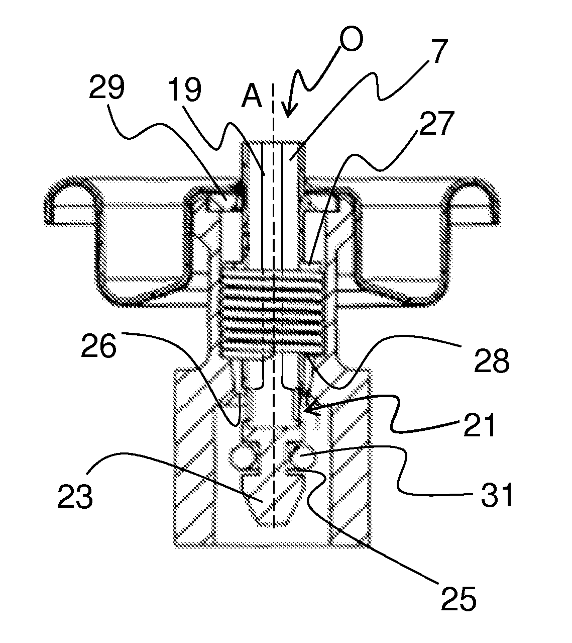
[0009]The present invention is directed to a valve used in both conventional and bag-on-valve aerosol container applications that allows a high flow rate of especially viscous substances. In a first embodiment of the present invention the valve includes a valve housing, a valve stem, and a spring or other biasing device that allows the valve stem to move relative to the valve housing. The valve stem is substantially hollow to allow the flow of product to and from a bag attached to the valve housing. There is a radial bore or bores and a seal near the bottom of the valve stem that dictate the passage and flow rate of pressurized product between the product container and the environment. The radial bore at the bottom or lower portion of the valve stem provides for flow directly from the product reservoir to the valve stem passage when a lower seal on the valve is opened. The valve stem passage is sealed by the lower seal or ring which is a separate sealing gasket or ring from the upper gasket. The lower seal may be located anywhere along the valve stem below the upper gasket and preferably at the bottom or lower portion of the valve stem facilitating communication to the product reservoir.

Problems solved by technology

Standard aerosol valve and gasket assemblies for dispensing pressurized product from a container have an inherent structural problem which limits the flow rate of product out of the container and through the valve stem.
The structural problem is two-fold, first the radial opening in the side of the valve stem must be smaller than the thickness of the gasket so that the opening is adequately covered in the closed valve position, otherwise there is a substantial risk of the product being able to escape even when the valve is closed by leakage through the radial opening.
Secondly, the larger the radial opening is on the upper portion of the valve stem where it is located in such conventional valve stems, the more the structural integrity of the valve stem is affected.
If the opening is too large the valve stem when subjected to axial and radial forces during depression by a user can fail and break, bend or otherwise permanently damage the valve stem.
Such restrictions in the size of the radial opening in the stem make it difficult to obtain high flow rates of product and a highly viscous product such as toothpaste cannot be dispensed without a sufficiently large passage in the valve stem.
Similarly, in other applications such as bag-on-valve assemblies, such valve stem openings create the same or similar structural issues.
An issue associated with the bag-on-valve technology is control of the volume flow of the product contents of the bag from the system to the environment.
This issue is especially compounded due to the different viscosities of the various products which manufacturers dispense from such bag-on-valve containers.
Handling the flow of a highly viscous substance such as for instance, toothpaste is particularly difficult in both conventional and bag-on-valve applications where the aerosol dispensing radial passages are particularly small in the 1.02 mm-1.52 mm (0.04-0.06 in.) range and there is no structural feasibility to make these holes larger with conventional valve structures.
The problem is to be able to accommodate larger dispensing openings in the valve beyond the 1.02 mm-1.52 mm (0.04-0.06 in.) range in order to accommodate higher flow rates and more viscous product.

Method used


Image

  • High flow aerosol valve
  • High flow aerosol valve
  • High flow aerosol valve

Examples


first embodiment

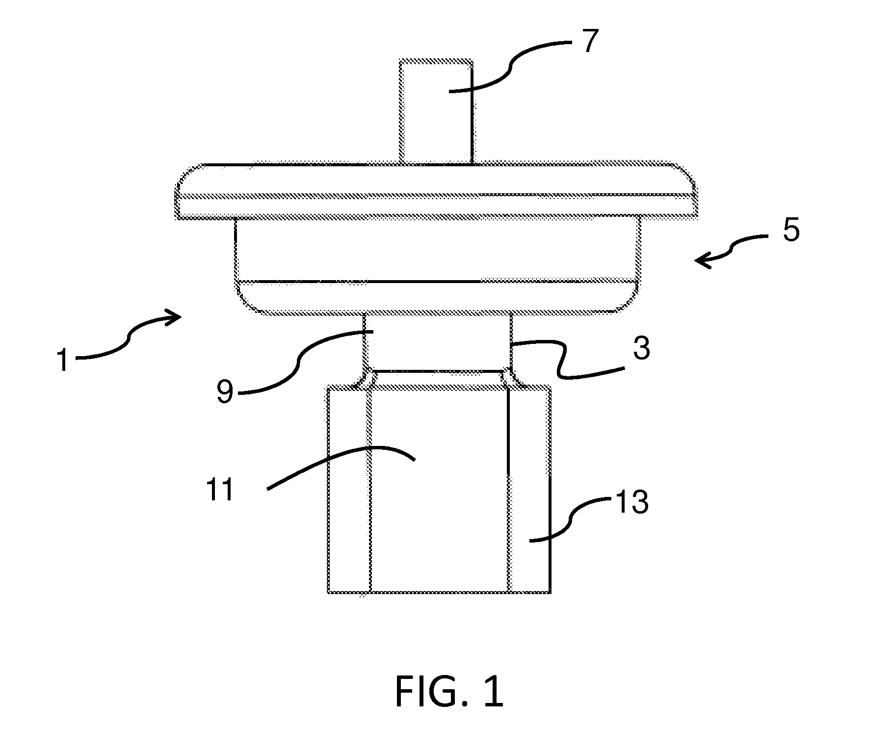
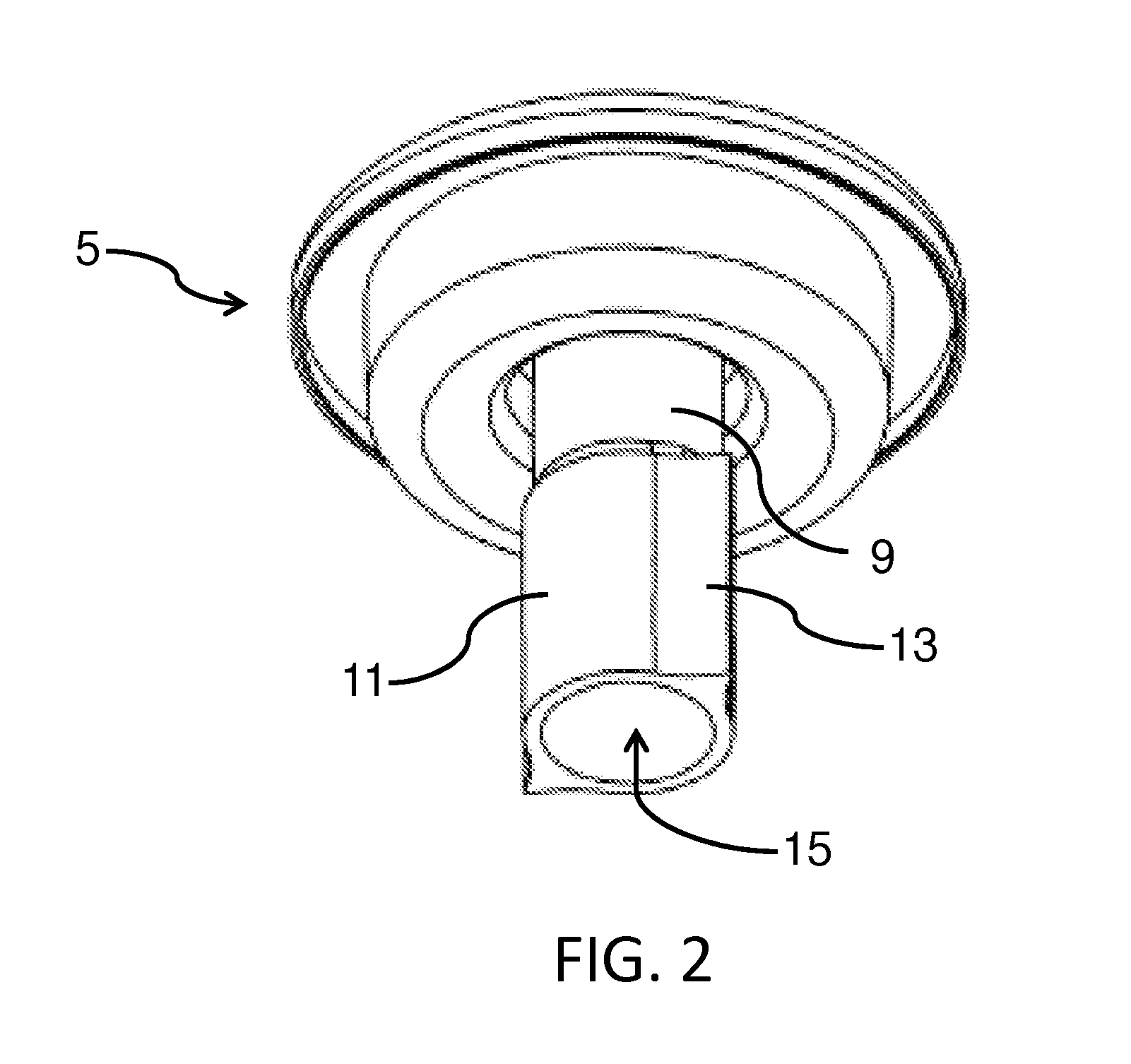
[0030]FIG. 1 illustrates a side view of an embodiment of the present invention illustrating the valve 1 in conjunction with the mounting cup 5 for a product containing can or container (not shown) in a bag-on-valve system. The valve stem 7 is parallel with and extends out of the valve housing 3 through the mounting cup 5. The valve housing 3 has multiple sections or portions that correspond to different functions for the bag-on-valve application. As is known in the art, a top portion of the valve housing is engaged generally by crimping with the mounting cup to secure the valve housing 3 to the mounting cup 5. The middle portion of the valve housing 3 is the spring cavity 9, which generally houses a spring for controlling dynamic movement between the valve stem 7 and the valve housing 3. The bottom portion 11 of the valve housing 3 can engage with either a dip tube, or as described in the first embodiment, with a product bag in the case of a bag-on-valve. In the present embodiment t...

second embodiment

[0040]Another important aspect of the present invention is the shape of the bores 35 which can facilitate control over dispensing of product at a high flow rate through the valve. FIG. 6 illustrates a side view of the valve stem 7 of the second embodiment with the bore 35 having a substantially circular shape. The bore 35 is a radial orifice in the sidewall of the valve stem 7, and adjacent the lower end thereof, which can be of a larger diameter than the 1.02 mm-1.52 mm (0.04-0.06 in.) diameter opening conventionally known, for example a diameter of between about 1.02 mm-3.81 mm (0.04-0.15 in) and more preferably in the range of about 2.03 mm-3.05 mm (0.08-0.12 in.) The larger bores 35 do not significantly affect the structural integrity of the valve stem 7 since the bores 35 are close to the bottom end of the valve stem where radial forces from depression and actuation of the valve stem 7 by a user are insignificant. Axial forces can significantly damage the valve stem where the r...


PUM

PropertyMeasurementUnit
cross-sectional areaaaaaaaaaaa
areaaaaaaaaaaa
flow rateaaaaaaaaaa

Abstract

The present invention is directed to a valve used in both conventional and bag-on-valve aerosol container applications that allows a high flow rate of especially viscous substances. Valves according to the present invention include a valve housing, a valve stem, and a spring or other biasing device that allows the valve stem to move relative to the valve housing. The valve stem is hollow to allow the flow of product to and from a bag attached to the valve housing. There are radial bores and a seal near the bottom of the valve stem that dictate the passage and flow rate of pressurized product between the product container and the environment. The bore shape and size can be selected to facilitate a high volume flow rate for highly viscous substances.

Description

FIELD OF THE INVENTION[0001]The present invention relates to a valve, in particular to a high flow aerosol valve used in both standard aerosol and bag-on-valve applications, and particularly to a valve having a housing that is supported by a mounting cup for a product container or can, and communicates with a product or product containment bag inside the can, where the radial opening of the valve is positioned closer to a lower seal of the valve stem rather than an upper seal or mounting cup gasket facilitating an increased flow rate for dispensing the product from the container and valve.BACKGROUND OF THE INVENTION[0002]Standard aerosol valve and gasket assemblies for dispensing pressurized product from a container have an inherent structural problem which limits the flow rate of product out of the container and through the valve stem. As is well known, the gasket which seals the conventional radial opening of the spring biased valve in the valve housing of conventional aerosol val...

Claims


Application Information

Patent Timeline
Patent Type & Authority Applications(United States)
IPC IPC(8): B65D83/00B23P17/04
CPCB65D83/48Y10T29/49826B65D83/62B05B1/3066
Inventor DAVIDEIT, DANIEL E.VERVILLE, KEVIN
Owner SUMMIT PACKAGING SYST
Why Eureka
Try Eureka