Wall mounting system

a wall mounting and system technology, applied in washstands, scaffold accessories, lighting supports devices, etc., can solve the problems of large cantilever loads, relatively heavy trophy total weight, and proving to be somewhat problemati

Active Publication Date: 2012-02-23
HEFFERNON TRAVIS
View PDF9 Cites 5 Cited by
  • Summary
  • Abstract
  • Description
  • Claims
  • Application Information

AI Technical Summary

Benefits of technology

[0008]The present invention overcomes the problems outlined above and provides a wall mounting system for securely mounting objects, such as high cantilever load objects, on a wall, where the object has a support member presenting a substantially flat rear face and a concavity extending forwardly from the rear face. The mounting system includes a bracket configured for attachment to the rear face, with a projecting segment extending into the concavity. The segment presents an inclined hanging surface. The system further includes a hanger configured for attachment to the wall, with an inclined support surface. The hanger is configured to extend into the projecting segment of the bracket, with the support surface and the hanging surface being disposed in face-to-face, mating engagement.

Problems solved by technology

As such, the complete trophy can be relatively heavy and can also create substantial cantilever loads when mounted on the wall.
This has proved to be somewhat problematic, because such conventional mounts are not designed to absorb the cantilever loads imposed by a big game trophy.
Even the most sturdy of picture-hanging mounts do not have sufficient structural integrity to ensure the safe mounting of a large big game trophy.
Moreover, traditional mounts have protruded outwardly from the backer board, possibly increasing instability of the hanging trophy.
There is accordingly a real and unsatisfied need in the art for a secure mounting system for high cantilever load objects, such as big game trophies, and which can be easily and safely installed on a variety of walls.

Method used


Image

  • Wall mounting system
  • Wall mounting system
  • Wall mounting system

Examples


Embodiment Construction

[0025]The present invention is susceptible of embodiment in many different forms. While the drawings illustrate, and the specification describes, certain preferred embodiments of the invention, it is to be understood that such disclosure is by way of example only. There is no intent to limit the principles of the present invention to the particular disclosed embodiments.

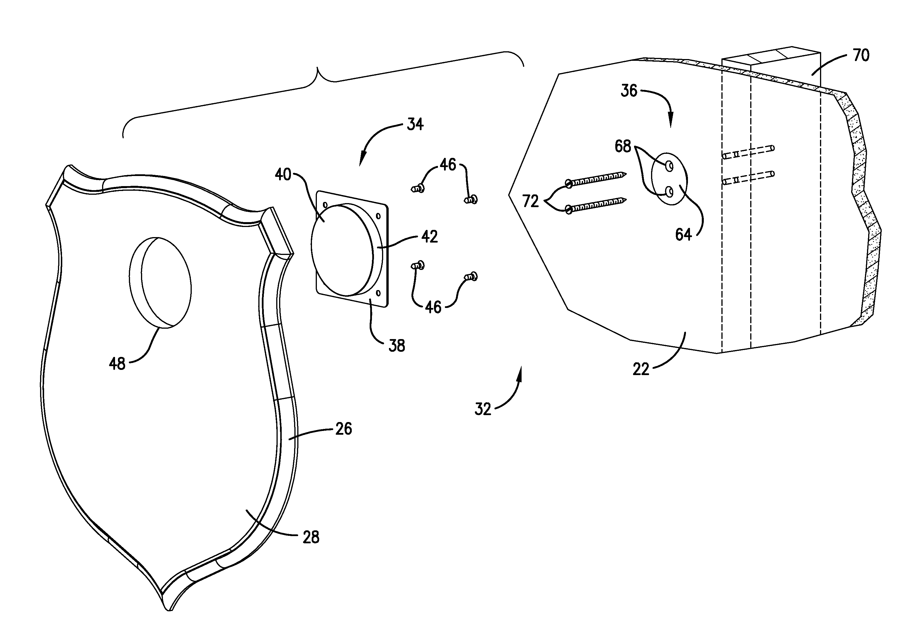
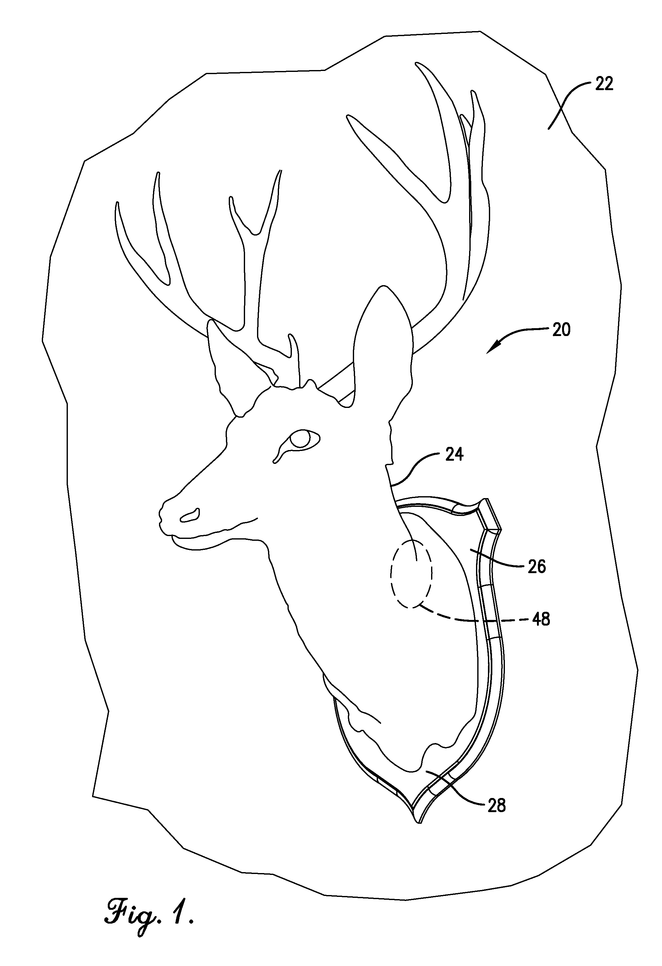
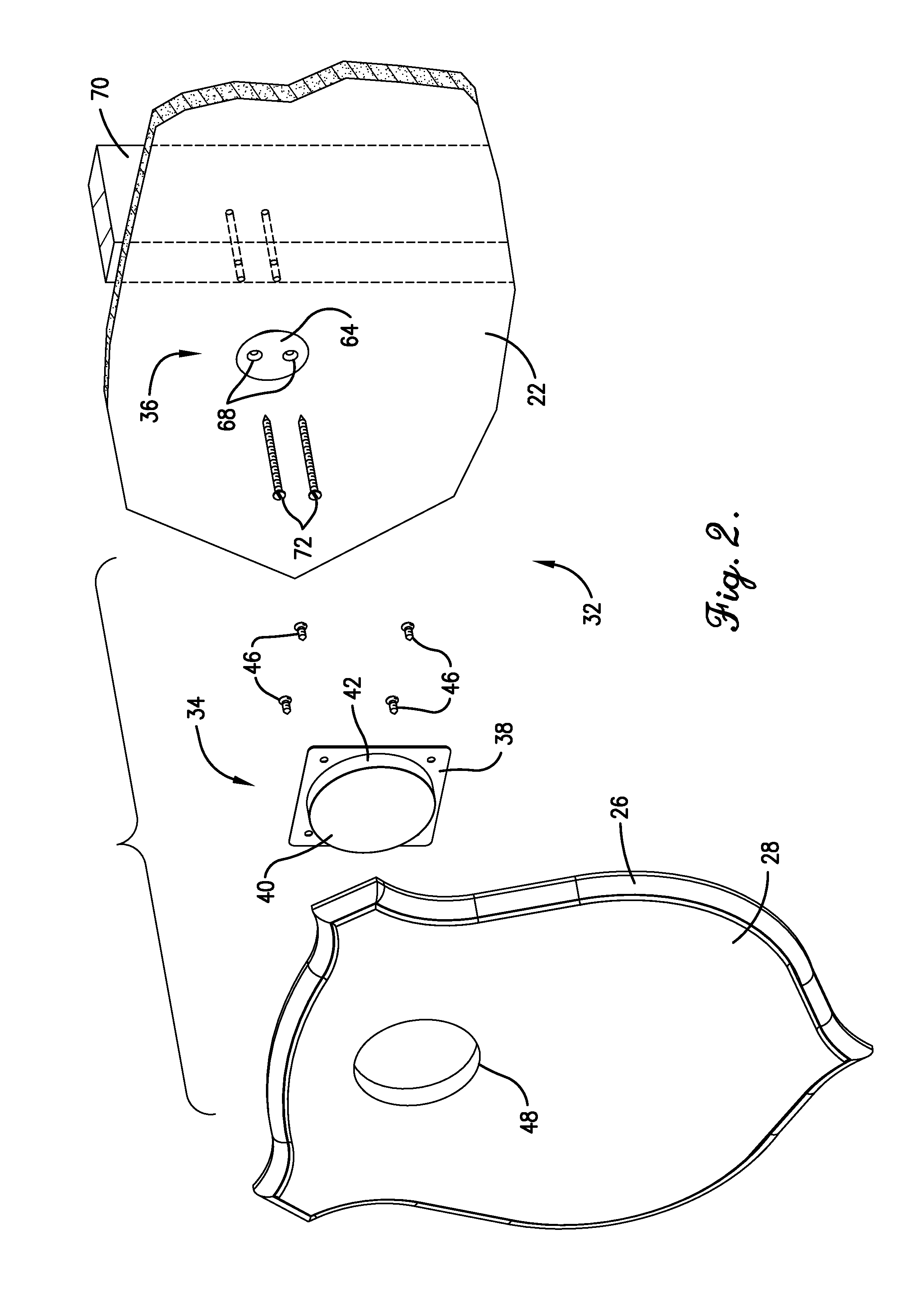
[0026]With reference now to the drawings, a high cantilever load object 20 designed for mounting on a wall 22 is illustrated in FIG. 1. In this instance, the object comprises a shoulder-mount big game trophy 24 secured to a shield or backer board 26. The backer board 26 presents a front face 28 and an opposed rear face 30 (see FIG. 4). Although the illustrated backer board 26 extends laterally outwardly from a base portion of the trophy 24, the backer board of an alternative mountable object may be simply attached to a rear end of a taxidermy manikin, as will be readily appreciated by one of ordinary skill in the art...


PUM


Abstract

A wall hanging system is provided for mounting of heavy, high cantilever load objects to an upright wall, such as a big game trophy comprising a backer board with a central opening. The system includes a bracket secured to the rear face of backer board and having a forwardly extending housing. The housing includes an arcuate, inclined, hanging wall section defining a mounting recess. The system also has a hanger including an inclined, arcuate, upper, support surface, which is received within the recess such that the hanging and support surfaces are disposed in mating engagement throughout a fore-and-aft depth of at least about one-quarter inch, and through an arc of at least about 120°.

Description

CROSS-REFERENCE TO RELATED APPLICATION[0001]The present application claims the benefit of and priority from U.S. Provisional Patent Application No. 61 / 375,655, filed Aug. 20, 2010, the entire disclosure of which is hereby incorporated by reference herein.BACKGROUND OF THE INVENTION[0002]1. Field of the Invention[0003]The present invention is broadly concerned with wall mounting systems for securely mounting high cantilever load objects on a wall to form a generally flush, secure, safe, and reliable mounting of the objects. More particularly, the invention is concerned with such mounting systems that are especially useful for mounting big game trophies, wherein the trophies include a backer board having a rear face concavity. Such mounting systems broadly include a bracket attachable to the rear face of the backer board with a projection extending into the concavity, and having a segment presenting an inclined hanging surface. A hanger also forms a part of the system and is configure...

Claims


Application Information

Patent Timeline
Patent Type & Authority Applications(United States)
IPC IPC(8): F16M13/02
CPCF16M13/02F16M11/041A47G1/1606
Inventor HEFFERNON, TRAVIS
Owner HEFFERNON TRAVIS
Why Eureka
Try Eureka