Supercharge Your Innovation With Domain-Expert AI Agents!

Communication system, communication units, and method for employing a pilot transmission scheme

Active Publication Date: 2012-02-23
INTELLECTUAL VENTURES HOLDING 81 LLC
View PDF11 Cites 5 Cited by
  • Summary
  • Abstract
  • Description
  • Claims
  • Application Information

AI Technical Summary

Benefits of technology

[0021]Accordingly, the invention seeks to mitigate, alleviate or eliminate one or more of the abovementioned disadvantages singly or in any combination.

Problems solved by technology

This degradation is often due to the action of the intervening radio propagation channel.
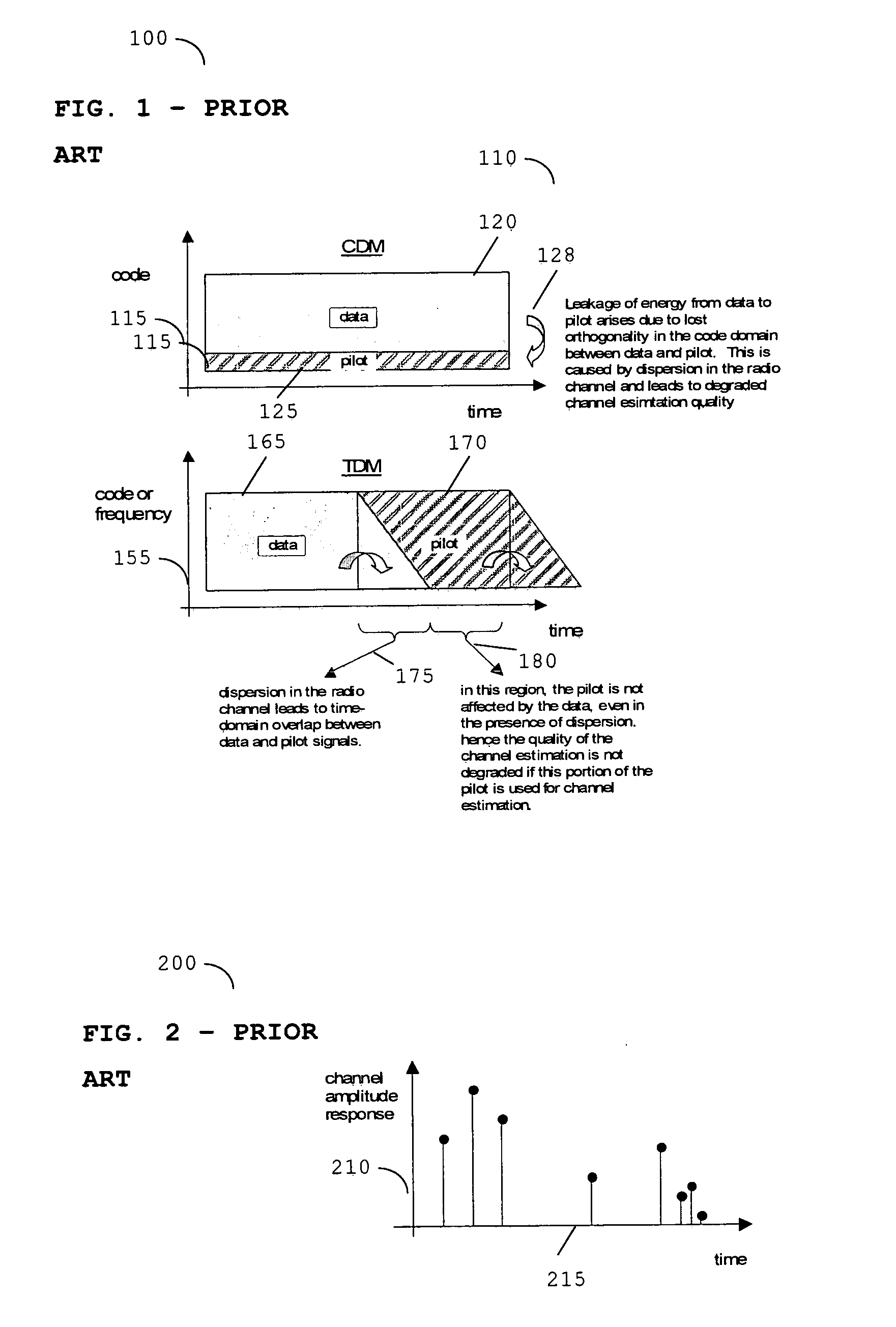
In particular, radio channels with a large amount of signal dispersion may significantly degrade the degree of orthogonality between pilot and data using a CDM technique.
As such, the use of CDM pilot signals can be less effective than would be desirable.
Orthogonality between the pilot signal and the data is again susceptible to degradation due to the overlap of energy between the two, which is caused by the delay spread in the radio propagation channel.
Large amounts of signal dispersion can occur due to the presence of multiple reflections in the radio channel.
In the absence of equalisation, the presence of multiple path reflections may severely degrade the radio link quality.
Therefore, it has been determined that the use of a CDM pilot for systems (such as the aforementioned SFN broadcast system) may not be overly appropriate in complex propagation channels.
Consequently, current techniques are suboptimal.

Method used


Image

  • Communication system, communication units, and method for employing a pilot transmission scheme
  • Communication system, communication units, and method for employing a pilot transmission scheme
  • Communication system, communication units, and method for employing a pilot transmission scheme

Examples


first embodiment

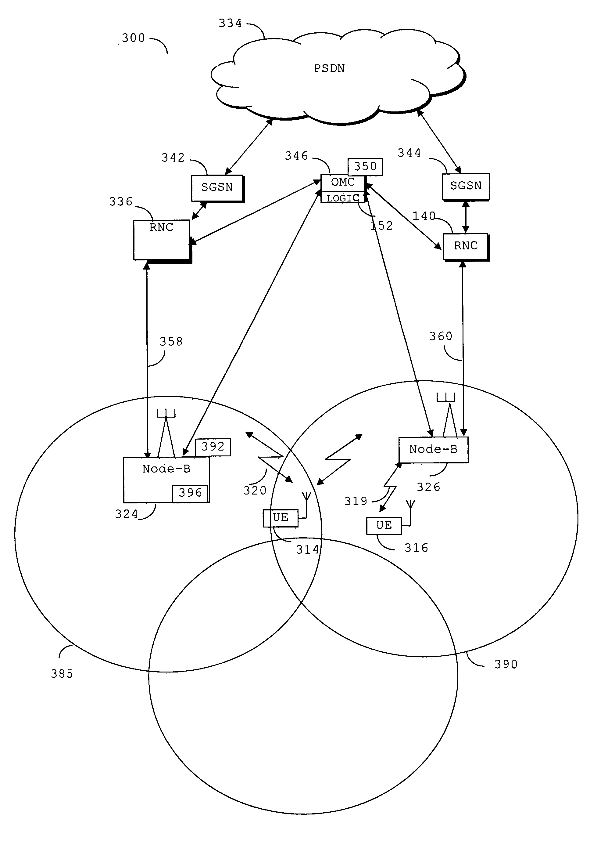
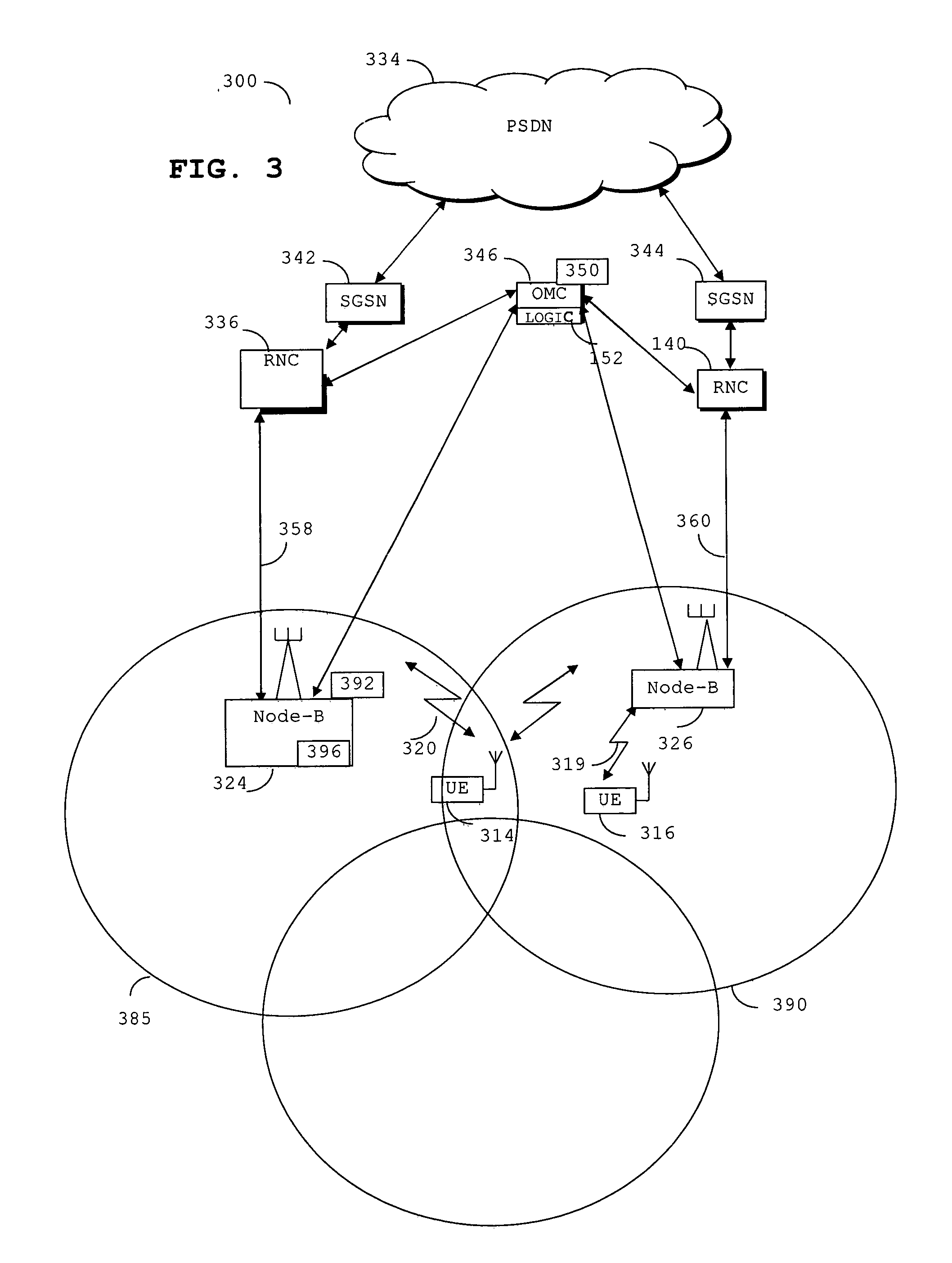
[0073]For example, in a first embodiment, let us consider that the wireless communication unit 400 is a Node B. In a Node-B context, the signal processor 408 may be adapted to generate a combined TOM pilot and CDM pilot dependent upon any number of ways to generate a TDM pilot and combine the TDM pilot in a composite signal that includes a CDM pilot sequence. In this example embodiment, the signal processor 408 may comprise modulator logic 436, for example if the TDM pilot is constructed using the OVSF construction method (e.g. as described later with respect to FIG. 9D). In this example embodiment, a TDM pilot may be generated and introduced into the transmission stream using an existing modulator with a new set of modulated symbols (which may sometimes hereinafter be termed pilot sequence ‘fragments’). The new set of modulated symbols may be introduced at the input of modulator logic 436 during a TDM pilot time region of one or more time slot, as will subsequently become apparent ...

second embodiment

[0076]In a second embodiment, let us consider that the wireless communication unit 400 is a UE. In a UE context, the signal processor 408 may be adapted to generate a combined TDM pilot and CDM pilot dependent upon a number of ways to generate the TDM pilot. In one example embodiment, the signal processor 408 may comprise channel estimator logic 430. In an application that uses legacy UEs, there would generally be an existing channel estimator that is based around estimation using the CDM pilot (e.g. a CPICH in a 3GPP system). In a second UE-based embodiment, a TDM pilot component may alternatively be instantiated using a new TDM-pilot channel estimation unit, and optionally combine the TDM pilot and CDM pilot outputs to provide an improved combined channel estimate, as illustrated and described further with reference to FIG. 11.

[0077]Alternatively, in the second UE-based embodiment, an existing CDM pilot channel estimator may be modified to create a new single channel estimation lo...


PUM


Abstract

A method of pilot-assisted data communication comprises transmitting a composite signal. The composite signal comprises data, a first pilot sequence with non-cyclic properties; and a second pilot sequence, such that the composite signal within a designated or pre-defined time region of one or more time slots exhibits a cyclic prefixed time domain structure. Both the first pilot sequence and second pilot sequence are transmitted in substantially this same designated or pre-defined time region in one or more time slots.

Description

FIELD OF THE INVENTION[0001]The invention relates to employing a pilot transmission scheme in a communication system and in particular, but not exclusively, to employing a pilot transmission scheme in a broadcast 3rd Generation Partnership Project (3GPP) cellular communication system.BACKGROUND OF THE INVENTION[0002]Currently, 3rd generation cellular communication systems are being rolled out to further enhance the communication services provided to mobile phone users. The most widely adopted 3rd generation communication systems are based on Code Division Multiple Access (CDMA) and Frequency Division Duplex (FDD) or Time Division Duplex (TDD) technology. In CDMA systems, user separation is obtained by allocating different spreading and / or scrambling codes to different users on the same carrier frequency and in the same time intervals. There may also be a time division multiple access (TDMA) component in CDMA systems, where user separation is also achieved by assigning different time...

Claims


Application Information

Patent Timeline
IPC IPC(8): H04B7/216H04J3/00H04B1/707H04J13/00H04J13/20
CPCH04B1/707H04B2201/70701H04L27/2607H04J13/20H04J13/0077H04B7/216H04L27/2613
Inventor ANDERSON, NICHOLAS WILLIAM
Owner INTELLECTUAL VENTURES HOLDING 81 LLC
Features
  • R&D
  • Intellectual Property
  • Life Sciences
  • Materials
  • Tech Scout
  • Unparalleled Data Quality
  • Higher Quality Content
  • 60% Fewer Hallucinations
Learn More