Optical ribbon and method of forming same

a technology of optical ribbons and fibers, applied in the field of optical ribbons, can solve the problems of reducing affecting the design of the optical ribbon, and limiting the geometry of the optical ribbon to a straight line, so as to improve the life of the ribbon, simplify the design constraints and design time, and increase the fiber density

Active Publication Date: 2012-02-23
MOLEX INC
View PDF4 Cites 11 Cited by
  • Summary
  • Abstract
  • Description
  • Claims
  • Application Information

AI Technical Summary

Benefits of technology

[0011]A further object of the present invention is to provide a generally flat optical ribbon which includes a curved section that can be installed with no intra-ribbon stress, increasing the life expectancy of the ribbon.
[0012]Yet a further object of the present invention is to provide a generally flat optical ribbon which includes a curved section that allows for precise, permanent and repeatable ribbon routing, ensuring clearance with other components on the printed wiring board.
[0013]An even further object of the present invention is to provide a generally flat optical ribbon which includes a curved section that enables higher fiber density and simplifies design constraints and design time.

Problems solved by technology

Generally, current optical ribbon technology limits ribbon geometry to a straight line.
When such fiber optic ribbons have to follow a curved path on an optical board, the accuracy of the routing is compromised.
These air flows may cause the optical ribbons vibrate against the abrasive surfaces, resulting in possible damage to the optical ribbon.
Furthermore, height limitations (if no curved ribbon cross-over is allowed) may create significant design constraints when the straight optical ribbons are used.
While this provides the ability to have a flat optical ribbon which can include a curved pattern, the substrates increase the cost of manufacturing the ribbon.

Method used


Image

  • Optical ribbon and method of forming same
  • Optical ribbon and method of forming same
  • Optical ribbon and method of forming same

Examples


Embodiment Construction

[0022]While the invention may be susceptible to embodiment in different forms, there is shown in the drawings, and herein will be described in detail, a specific embodiment with the understanding that the present disclosure is to be considered an exemplification of the principles of the invention, and is not intended to limit the invention to that as illustrated and described herein.

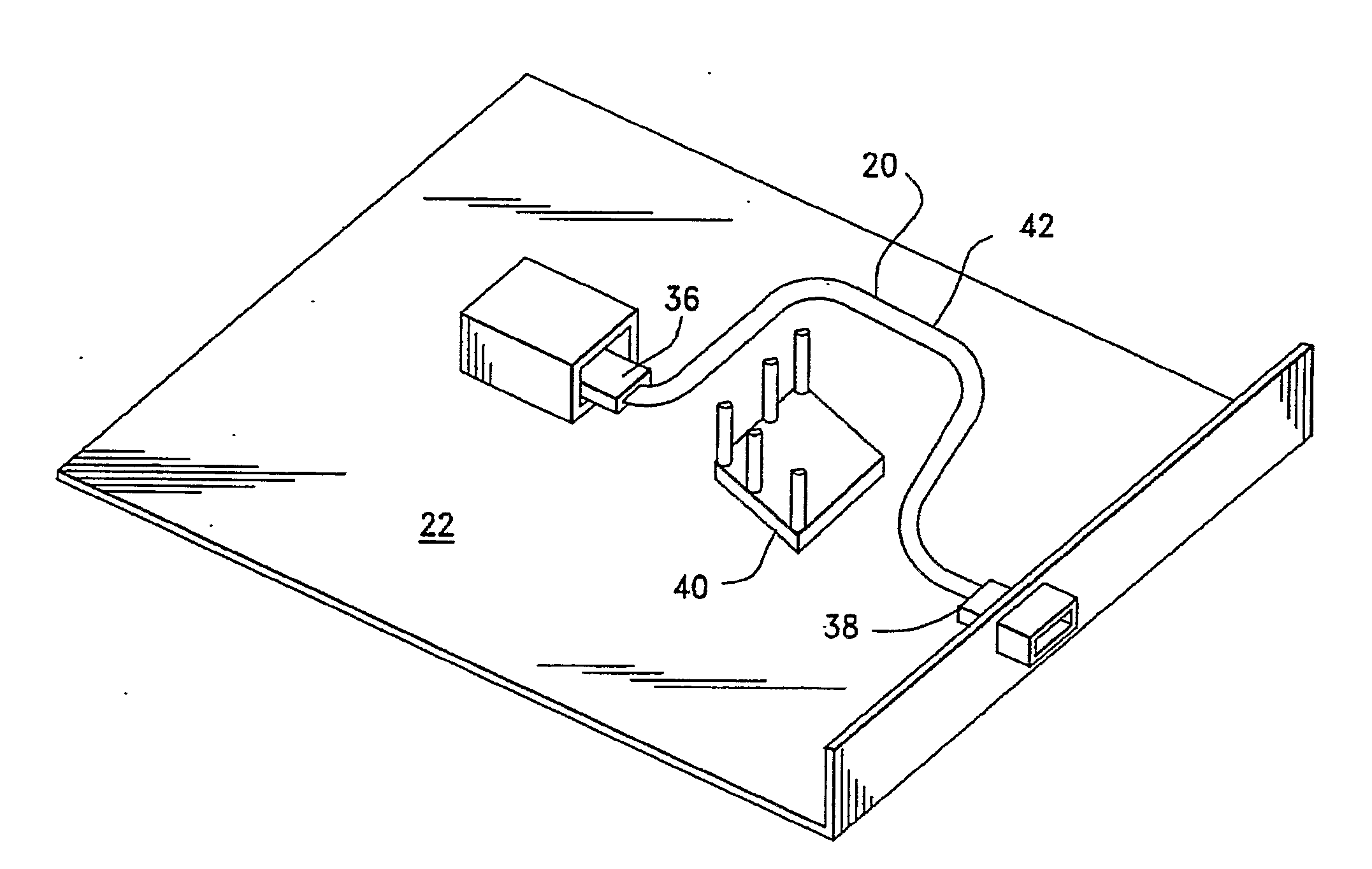
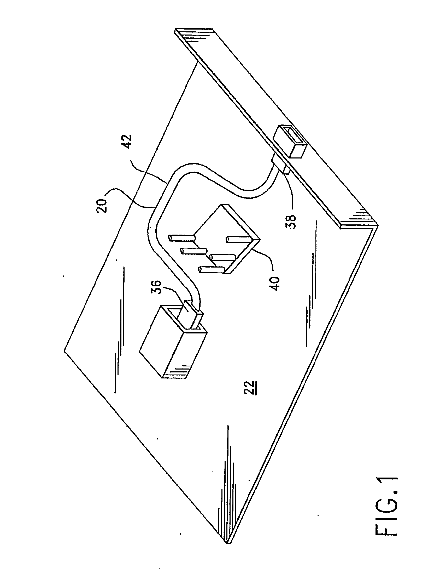
[0023]An optical ribbon 20 is provided for use in an optical flex circuit and / or cable assembly. The optical ribbon 20 may be mounted on a printed wiring board 22.

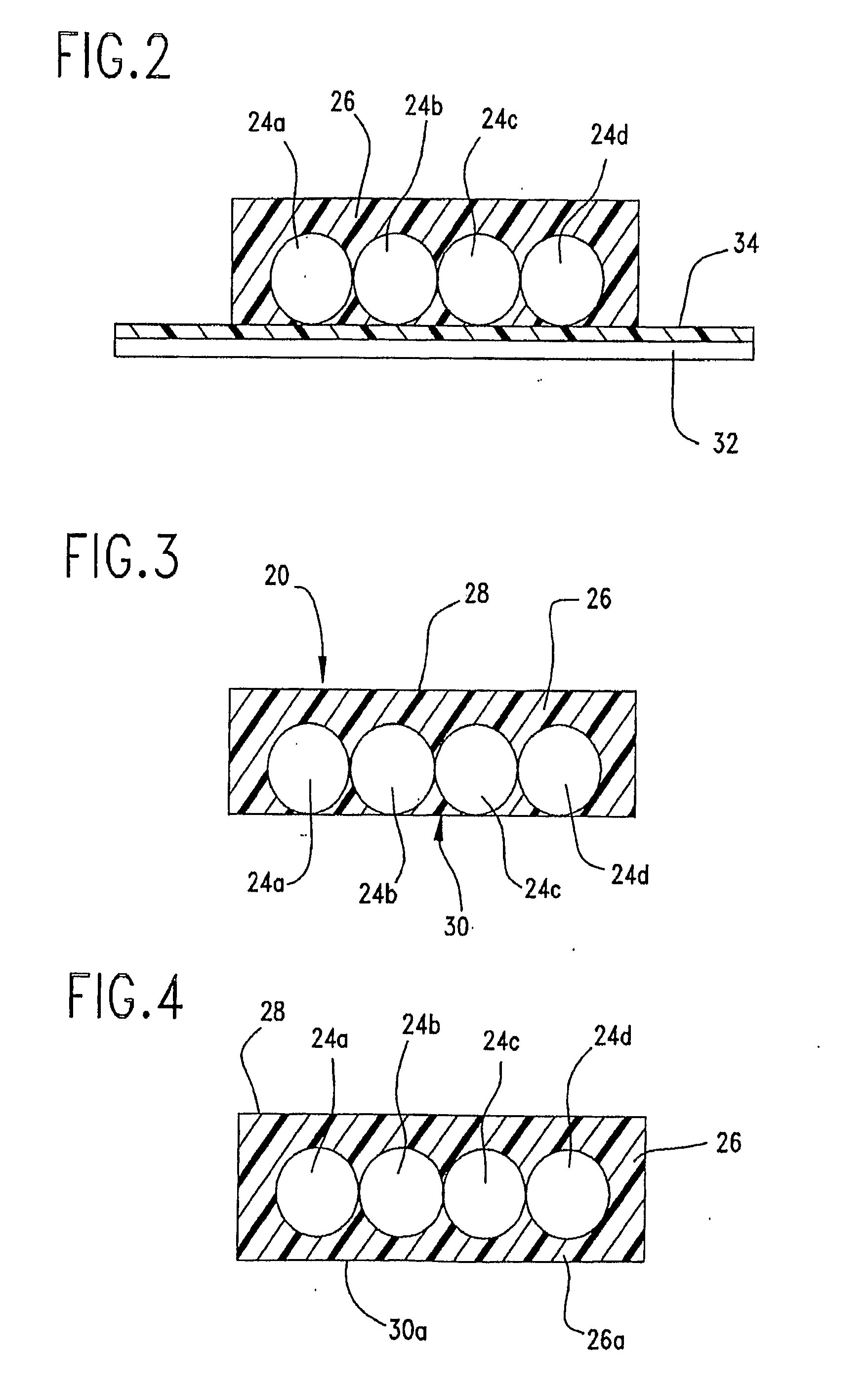
[0024]The optical ribbon 20 includes at least one optical fiber 24a which is substantially encapsulated with a conformal coating 26 to form the optical ribbon 20. Preferably, at least two optical fibers 24a, 24b are provided and are positioned side-by-side to each other to form a flat ribbon. The term “flat” as used herein means that the upper surface 28 of the optical ribbon 20 is substantially planar, the lower surface 30 of the optical ribbo...


PUM

PropertyMeasurementUnit
shapeaaaaaaaaaa
flexibleaaaaaaaaaa
abrasiveaaaaaaaaaa

Abstract

An optical ribbon (20) includes at least one optical fiber and a conformal coating at least substantially encapsulating said at least one optical fiber. The optical ribbon is flat and has a generally curved section (42) which can be routed around components (40) on a printed wiring board (22) or can be used as a built-in ferrule retermination loop.

Description

FIELD OF THE INVENTION[0001]This invention is generally directed to an optical ribbon in an optical flex circuit and / or cable assembly.BACKGROUND OF THE INVENTION[0002]Generally, current optical ribbon technology limits ribbon geometry to a straight line. When such fiber optic ribbons have to follow a curved path on an optical board, the accuracy of the routing is compromised. In some cases, the fiber optic ribbons may rub against abrasive surfaces such as FR4 laminate or heat sinks. In particular, as telecom system components, such as ASICs and optical transceivers, generate ever-increasing amounts of heat, fans are used to cool the components by generating powerful air flows. These air flows may cause the optical ribbons vibrate against the abrasive surfaces, resulting in possible damage to the optical ribbon.[0003]Forcing prior art optical ribbons into curved paths, or installing the ribbon in a way that forces the optical ribbon to bend in any plane other than perpendicular to i...

Claims


Application Information

Patent Timeline
Patent Type & Authority Applications(United States)
IPC IPC(8): G02B6/44B23P17/04
CPCG02B6/43Y10T29/49982G02B6/448G02B6/4403
Inventor TROTABAS, REMYTKACH, SEMYONGENCHANOK, GENNADY
Owner MOLEX INC
Why Eureka
Try Eureka