Method and Apparatus for Deriving Parameters of Optical Paths in Optical Networks Using Two-wavelength OTDR and a Wavelength-Dependent Reflective Element

Active Publication Date: 2012-02-23
EXFO
View PDF27 Cites 61 Cited by
  • Summary
  • Abstract
  • Description
  • Claims
  • Application Information

AI Technical Summary

Benefits of technology

[0013]An object of the present invention is to mitigate the deficiencies of known methods of using OTDR and a reflective element to

Problems solved by technology

A drawback of the afore-described prior art methods is that the measured OTDR traces may also comprise localized events that arise from reflective events such as high splitter return loss, connectors, etc., in one or more of the optical paths that is/are not common with all the other optical paths (i.e. not in the F1 cable of a PON network, for instance).
It may be difficult to identify initially which localized reflective events are from reflective elements installed for HRD purposes and which localized reflective events are from other network reflective events.
Initial characterization of the point-to-multipoint network before commissioning may then be difficult, and the measurement of optical path loss in a particular multipoint link may become unreliable.
Unfortunately, however, the relatively large reflections from such a

Method used


Image

  • Method and Apparatus for Deriving Parameters of Optical Paths in Optical Networks Using Two-wavelength OTDR and a Wavelength-Dependent Reflective Element
  • Method and Apparatus for Deriving Parameters of Optical Paths in Optical Networks Using Two-wavelength OTDR and a Wavelength-Dependent Reflective Element
  • Method and Apparatus for Deriving Parameters of Optical Paths in Optical Networks Using Two-wavelength OTDR and a Wavelength-Dependent Reflective Element

Examples


Embodiment Construction

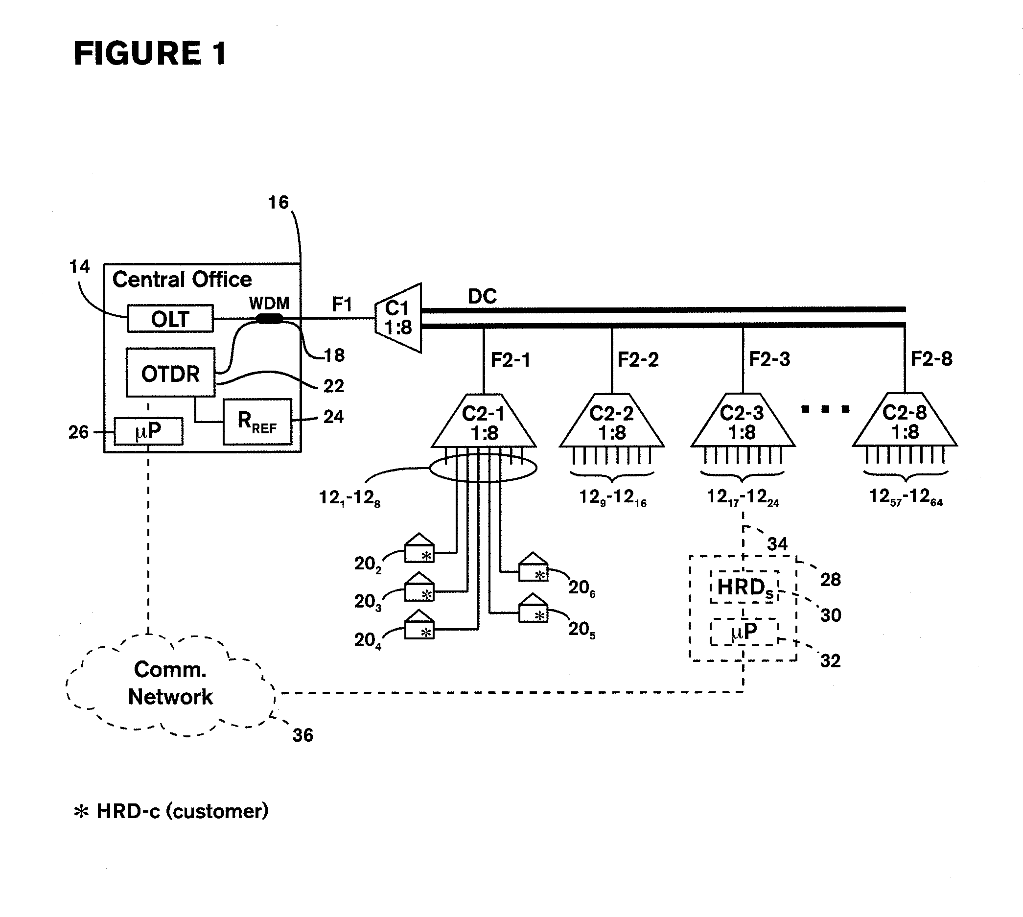
[0045]FIG. 1 illustrates a portion 10 of an optical network, specifically a Passive Optical Network (PON), comprising multiple “drop” fibers 12 connected to an Optical Line Terminal (OLT) 14 in a central office 16. For purposes of illustration, FIG. 1 illustrates a network having only sixty-four drop fibers 121 to 1264, in eight groups of eight. Each group of eight drop fibers is connected by a respective one of eight 1×8 couplers C2-1 to C2-8 and a corresponding one of eight distribution fibers F2-1 to F2-8, in a distribution cable DC, to a further 1×8 coupler C1 which is connected to the OLT 14 by way of a single (common) fiber F1 and a wavelength-division multiplexer (WDM) 18. This WDM 18 substantially separates, onto distinct fibers, light at a wavelength corresponding to the normal operating wavelengths range of the PON (e.g. 1310 nm, 1490 nm, 1550 nm) from light propagating in the same fiber corresponding to U-band wavelengths range of the OTDR (e.g. 1625-1675 nm), or, inverse...


PUM


Abstract

A method of distinguishing a wavelength-dependent reflective element (HRD) from wavelength-independent events in an optical network, the reflective element (HRD) being highly-reflective at a first predetermined wavelength (λ1) and significantly less reflective at least one other predetermined wavelength (λ2), comprising the steps of: connecting the wavelength-dependent reflective element (HRD) to said optical path at a first position, and, using an optical time domain reflectometer (22) connected to said optical path at a position remote from said reflective element, launching into said optical path light at said first wavelength (λ1) and at said second wavelength (λ2), detecting corresponding backreflected light from said optical paths and obtaining therefrom first and second OTDR traces (OTDR-λ1, OTDR-λ2) corresponding to said first (λ1) and second (λ2) wavelengths, respectively, of detected backreflected light as a function of optical distance from said point; comparing the first and second OTDR traces to distinguish a peak corresponding to said wavelength-dependent reflective element from peaks corresponding to said wavelength-independent reflective events; and outputting at least one parameter value of the distinguished peak as a measure of a parameter of said wavelength-dependent reflective element.

Description

CROSS-REFERENCE TO RELATED APPLICATIONS[0001]This application claims priority from U.S. Provisional Patent Application No. 61 / 136,955 filed 17 Oct. 2008, the entire contents of which are incorporated herein by reference.TECHNICAL FIELD[0002]This invention relates to a method and apparatus for deriving one or more parameters of a selected optical path, e.g. a link, in an optical network using optical time domain reflectometry and at least one highly-reflective element associated with the selected optical path.BACKGROUND ART[0003]It is known for supervisory systems of point-to-point optical networks to use Optical Time Domain Reflectometer (OTDR) measurements to monitor optical links, specifically each joint (splices or connectors) in each link, to locate a fault when it occurs.[0004]In point-to-multipoint optical networks, such as Passive Optical Networks (PON), however, respective ends of the network links are connected in common at the single point at or adjacent a network element ...

Claims


Application Information

Patent Timeline
IPC IPC(8): H04J14/00
CPCH04J14/0282H04B10/0795H04B10/25H04B10/071
Inventor PERRON, STEPHANE
Owner EXFO
Why Eureka
Try Eureka