Charging apparatus using charging tube and image forming apparatus having the same

a charging apparatus and charging tube technology, applied in the direction of electrographic process apparatus, instruments, corona discharge, etc., can solve the problems of increasing the size of the image forming apparatus, the disadvantage of generating ozone, and the increase of the manufacturing cos

Inactive Publication Date: 2012-02-23
HEWLETT PACKARD DEV CO LP
View PDF5 Cites 3 Cited by
  • Summary
  • Abstract
  • Description
  • Claims
  • Application Information

AI Technical Summary

Benefits of technology

[0010]The foregoing and / or other aspects are achieved by providing a charging apparatus including: a charging tube which has an outer surface contacting a photoconductive medium and electrically charges a surface of the photoconductive medium, a shaft which is disposed in the charging tube and to which a charging voltage is applied, and a conductive member which is connected to the shaft and contacts an inner surface of the charging tube. A friction coefficient between the conductive member and the inner surface of the charging tube may be less than a friction coefficient between the photoconductive medium and the outer surface of the charging tube, so that a slip phenomenon of the charging tube is prevented.
[0022]The charging apparatus may further include a meandering prevention unit to prevent the charging tube from meandering in a lengthwise direction of the shaft.

Problems solved by technology

The charging apparatus using the corona discharge has the advantage of charging a photoconductive medium uniformly, but has the disadvantage of generating a discharge product such as ozone.
Therefore, an extra apparatus for processing the discharge product such as ozone is required and thus a size of the image forming apparatus increases and a manufacturing cost also increases.
However, there is a noise problem because the charging roller operates in contact with the photoconductive medium.
Also, some of the low molecules forming the charging roller migrate to the photoconductive medium and thus there is a problem that the photoconductive medium is contaminated.

Method used


Image

  • Charging apparatus using charging tube and image forming apparatus having the same
  • Charging apparatus using charging tube and image forming apparatus having the same
  • Charging apparatus using charging tube and image forming apparatus having the same

Examples


Embodiment Construction

[0038]Reference will now be made in detail to the present embodiments, examples of which are illustrated in the accompanying drawings, wherein like reference numerals refer to the like elements throughout. The embodiments are described below in order to explain the embodiments by referring to the figures. It should be understood that various features are not drawn to scale and the dimensions of the various features may be arbitrarily increased or reduced for clarity of discussion.

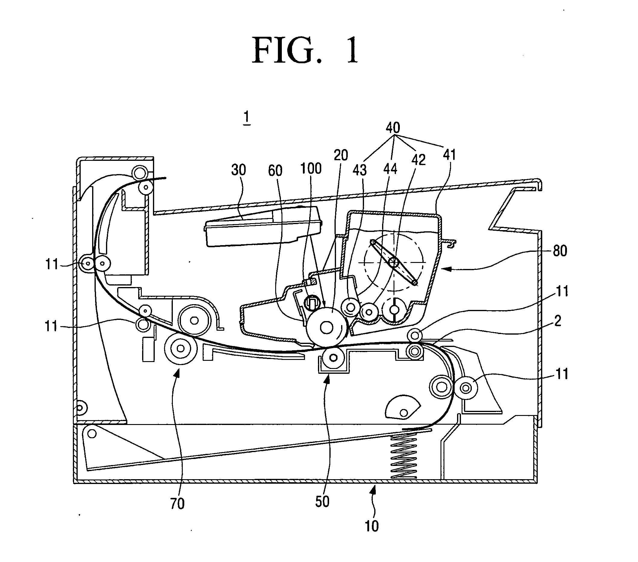
[0039]FIG. 1 is a schematic view illustrating an image forming apparatus 1 according to an exemplary embodiment. The image forming apparatus 1 may be diverse apparatuses for forming a predetermined image on a printing medium such as printers, facsimile machines, copiers, and multifunction peripherals. FIG. 1 also illustrates an advancing path 2 of the printing medium.

[0040]A paper feeding apparatus 10 stores the printing medium such as paper therein. The printing medium is conveyed by a plurality of conveya...


PUM


Abstract

A charging apparatus including a charging tube which has an outer surface contacting a photoconductive medium and electrically charges a surface of the photoconductive medium, a shaft which is disposed in the charging tube and to which a charging voltage is applied, and a conductive member which is connected to the shaft and contacts an inner surface of the charging tube. A friction coefficient between the conductive member and the inner surface of the charging tube may be less than a friction coefficient between the photoconductive medium and the outer surface of the charging tube, so that a slip phenomenon of the charging tube is prevented.

Description

CROSS-REFERENCE TO RELATED APPLICATION[0001]This application claims the benefit of Korean Patent Application No. 10-2010-0080358, filed on Aug. 19, 2010, in the Korean Intellectual Property Office, the disclosure of which is incorporated herein by reference.BACKGROUND[0002]1. Field[0003]Aspects relate to an image forming apparatus, and more particularly, to a charging apparatus using a charging tube.[0004]2. Description of the Related Art[0005]An image forming apparatus such as a printer, a facsimile machine, a copier, and a multifunction peripheral forms a predetermined image on a printing medium using electrophotography. Such an image forming apparatus generally carries out a charging process, a laser scanning process, a developing process, a transferring process, and a fusing process, in order to form an image. In the charging process, a charging apparatus electrically charges a photoconductive medium with a predetermined electric potential. In the laser scanning process, a laser...

Claims


Application Information

Patent Timeline
Patent Type & Authority Applications(United States)
IPC IPC(8): G03G15/02
CPCG03G15/0233
Inventor JEON, IN-CHEOLDO, KI-JAEJOO, JONG-HWALEE, YONG-HOONPARK, SANG-JIN
Owner HEWLETT PACKARD DEV CO LP
Why Eureka
Try Eureka