Planter that can be raised, lowered and locked to a vertical support structure

a planter and vertical support technology, applied in the field of planters, can solve the problems of pedestrian slipping and falling, and achieve the effects of facilitating raising, lowering, locking and releasing the planter assembly, and facilitating the draining and cleaning

Active Publication Date: 2012-03-01
HOGAN JAMES
View PDF8 Cites 26 Cited by
  • Summary
  • Abstract
  • Description
  • Claims
  • Application Information

AI Technical Summary

Benefits of technology

[0025]To solve one or more of the problems set forth above, in an exemplary implementation of the invention, a variable controlled planter system allows for the raising, lowering, holding, locking and releasing of a planter on a vertical support structure. The planter assembly may include a carriage, to which one or more planters is attached. The carriage facilitates raising, lowering, holding, locking and releasing of planter assemblies. Guides such as cables, rollers, sliders, bristles, gaskets, carpet and registration pins maintain space between the vertical support and planter assembly and facilitate raising and lowering. A tether guided over a pulley may be retracted or extended by winding it around or unwinding it from a winch, cleat or windlass to causes the planter assembly to rise or descend. When raised to a locking height...

Problems solved by technology

Artificial plants do not drop leaves and flowers that may otherwise create a ...

Method used


Image

  • Planter that can be raised, lowered and locked to a vertical support structure
  • Planter that can be raised, lowered and locked to a vertical support structure
  • Planter that can be raised, lowered and locked to a vertical support structure

Examples


Embodiment Construction

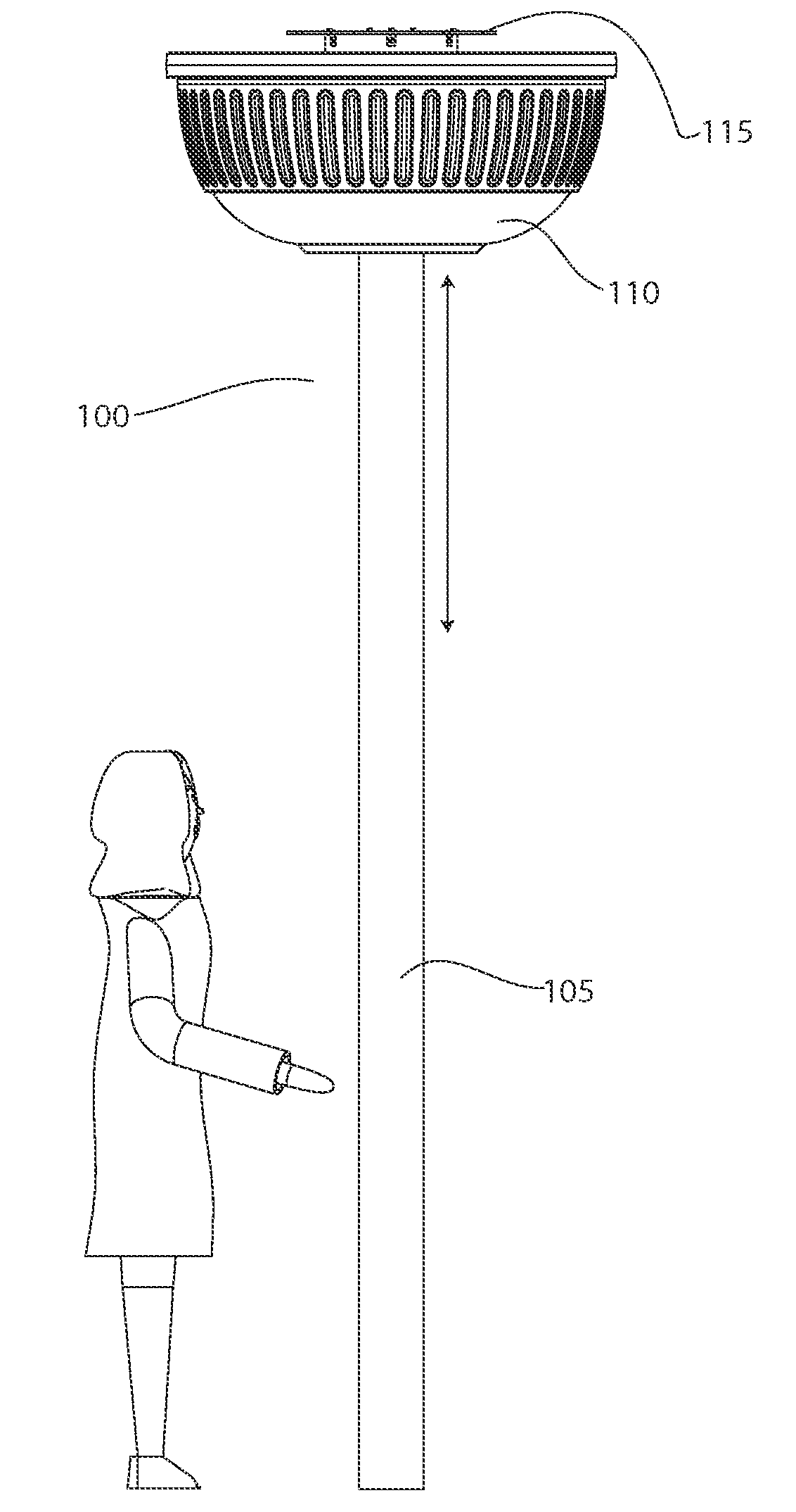
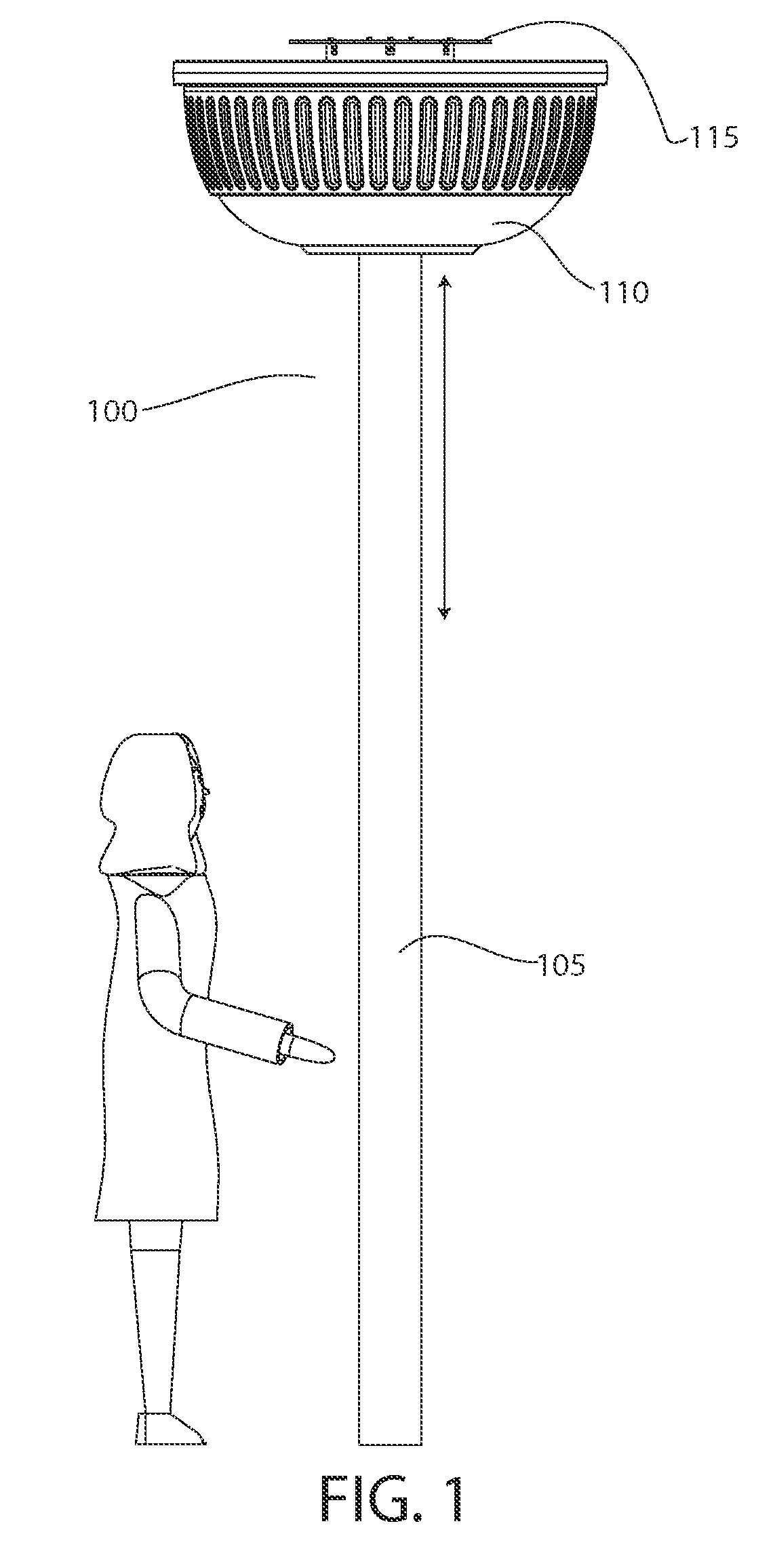
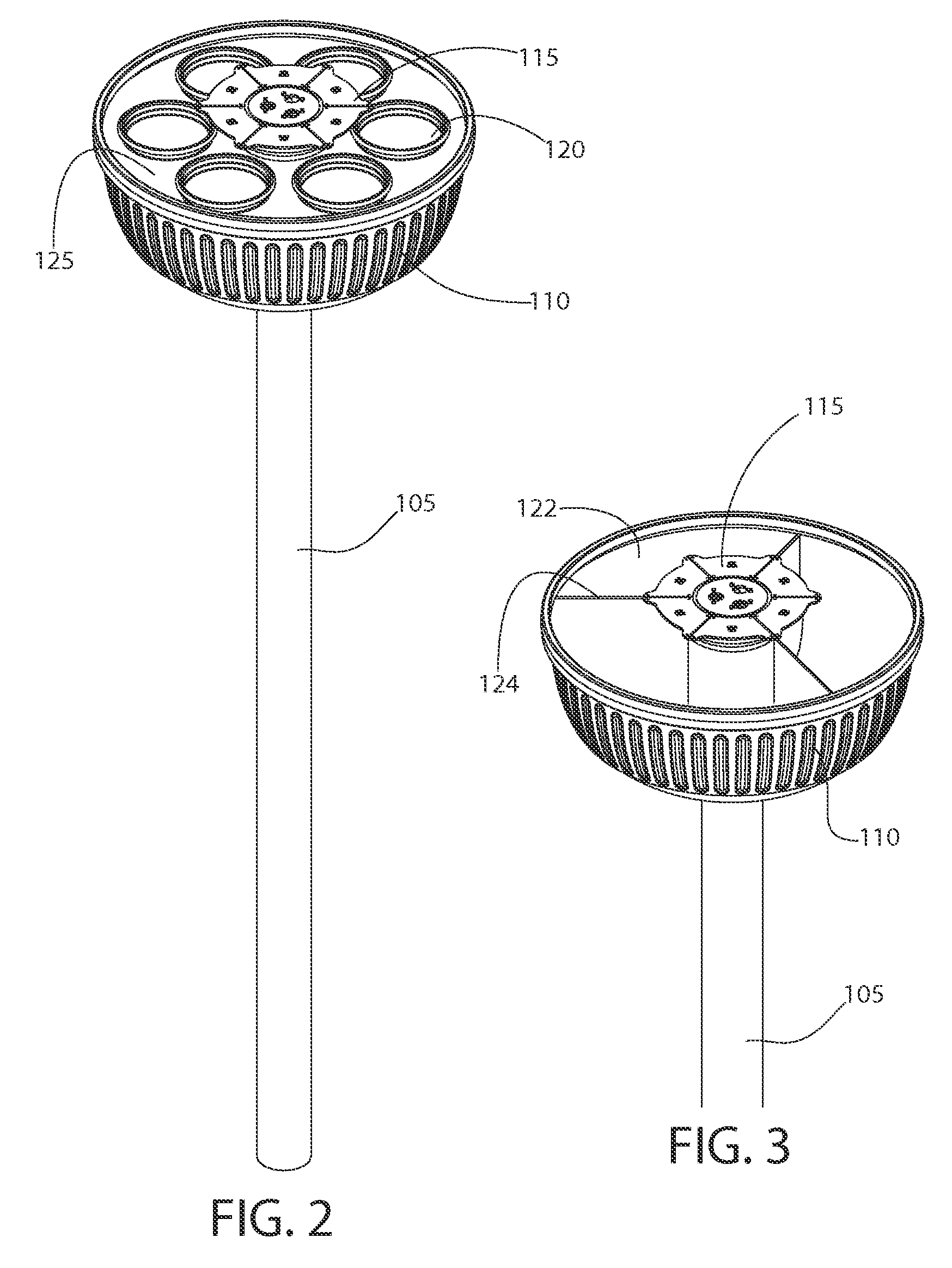
[0158]With reference to the Figures and the description provided below, exemplary variable controlled planter systems allowing for the raising, lowering, holding, locking and releasing of a planter on a vertical support structure are provided. In one embodiment, at least one pulley defines the highest position. A tether guided by the pulley is directly or indirectly coupled to a winch, cleat or windlass at one end. At the opposite end, the tether is directly or indirectly coupled to a planter assembly. The planter assembly may include a carriage, to which one or more planters is attached. The carriage facilitates raising, lowering, holding, locking and releasing of planter assemblies. The tether may be retracted by winding it around the winch, cleat or windlass and extended by unwinding it from the winch, cleat or windlass, or other means. Retracting the tether causes the planter assembly to rise. Extending the tether lowers the planter assembly. The winch may include a control, suc...


PUM


Abstract

Planter systems allow for the raising, lowering, holding, locking and releasing of a planter on a vertical support structure. The planter assembly may include a carriage, to which one or more planters is attached. Guides such as cables, rollers, sliders, bristles, gaskets, carpet and registration pins maintain space between the vertical support and planter assembly and facilitate raising and lowering. A tether guided over a pulley may be retracted or extended by winding it around or unwinding it from a winch, cleat or windlass to causes the planter assembly to rise or descend. When raised to a locking height, the planter assembly causes a mechanical locking mechanism associated with the planter assembly to move into a locking position, securing the planter assembly to the vertical support. Further raising releases the locking mechanism. Attachable items such as banners, flags, hangers and the like may be coupled to the carriage. Optional irrigation supplies water to the planter assembly and/or surrounding terrain. The planter may be unitary or a plurality of assembled planter components or sections. Drain and cleanout ports facilitate draining and cleaning of the planter assembly. An optional waterfall embodiment includes a reservoir section with overflow ports to drain water into a lower reservoir at the base of the vertical support, from which a pump supplies the water back to the reservoir section of the planter assembly. A plurality of conduits for electrical, data and plumbing extend through the vertical support.

Description

RELATED APPLICATION[0001]This application is a continuation in part and claims the benefit of priority of U.S. Nonprovisional application Ser. No. 11 / 868,534, filed Oct. 8, 2007, the entire contents, including declarations, of which are incorporated herein by this reference, and a continuation in part and claims the benefit of priority of U.S. Nonprovisional application Ser. No. 12 / 026,553 filed Feb. 2, 2008, and a continuation in part and claims the benefit of priority of U.S. Nonprovisional application Ser. No. 12 / 164,075 filed Jun. 29, 2008, the entire contents, including declarations, of which are incorporated herein by this reference.FIELD OF THE INVENTION[0002]This invention generally relates to planters, and, more particularly, to variable controlled planter systems allowing for the raising, lowering, holding, locking and releasing of planters on poles or other elongated support structures.BACKGROUND[0003]Planters (i.e., open vessels for holding plants) have been around for m...

Claims


Application Information

Patent Timeline
IPC IPC(8): A01G9/02
CPCA01G9/022A47G7/044A47G7/041A01G27/003
Inventor HOGAN, JAMES
Owner HOGAN JAMES
Why Eureka
Try Eureka