Duplex tab obstacles for enhancement of deflagration-to-detonation transition

a detonation and transition technology, applied in the field of dual tab obstacles for enhancing the deflagration-to-detonation transition, can solve the problems of relative high pressure drop and require cooling, and achieve the effects of flame acceleration, and enhancing the turbulence of the fluid flow

Active Publication Date: 2012-03-01
GENERAL ELECTRIC CO
View PDF19 Cites 17 Cited by
  • Summary
  • Abstract
  • Description
  • Claims
  • Application Information

AI Technical Summary

Benefits of technology

[0005]Briefly, in accordance with one embodiment, a detonation chamber for a pulse detonation combustor is provided. The detonation chamber includes a plurality of duplex tab obstacles disposed on at least a portion of an inner surface of the detonation chamber. The duplex tab obstacles are further configured enhance a turbulence of a fluid flow and flame acceleration through the detonation chamber.
[0006]In accordance with another embodiment, a detonation chamber for a pulse detonation combustor is provided. The detonation chamber includes a plurality of duplex tab obstacles disposed on at least a portion of an inner surface of the detonation chamber. The plurality of duplex tab obstacles are configured having compound radial and circumferential inclination therein to enhance a turbulence of a fluid flow and flame acceleration through the detonation chamber. Each of the plurality of duplex tab obstacles includes at least a pair of tabs. The detonation chamber further includes an inlet and an outlet. The plurality of duplex tab obstacles are disposed on at least a portion of an inner surface of the detonation chamber between the inlet and the outlet.
[0007]In accordance with another embodiment, a pulse detonation combustor is provided. The pulse detonation combustor includes at least one detonation chamber; an oxidizer supply section for feeding an oxidizer into the detonation chamber; a fuel supply section for feeding a fuel into the detonation chamber; and an igniter for igniting a mixture of the gas and the fuel in the detonation chamber. The detonation chamber comprises a plurality of duplex tab obstacles disposed on an inner surface of the detonation chamber. The plurality of duplex tab obstacles are provided to enhance a turbulence of a fluid flow and flame acceleration through the detonation chamber.

Problems solved by technology

The problem with obstacles for cyclic detonation devices is that they have relatively high pressure drop, and require cooling.

Method used


Image

  • Duplex tab obstacles for enhancement of deflagration-to-detonation transition
  • Duplex tab obstacles for enhancement of deflagration-to-detonation transition
  • Duplex tab obstacles for enhancement of deflagration-to-detonation transition

Examples


Embodiment Construction

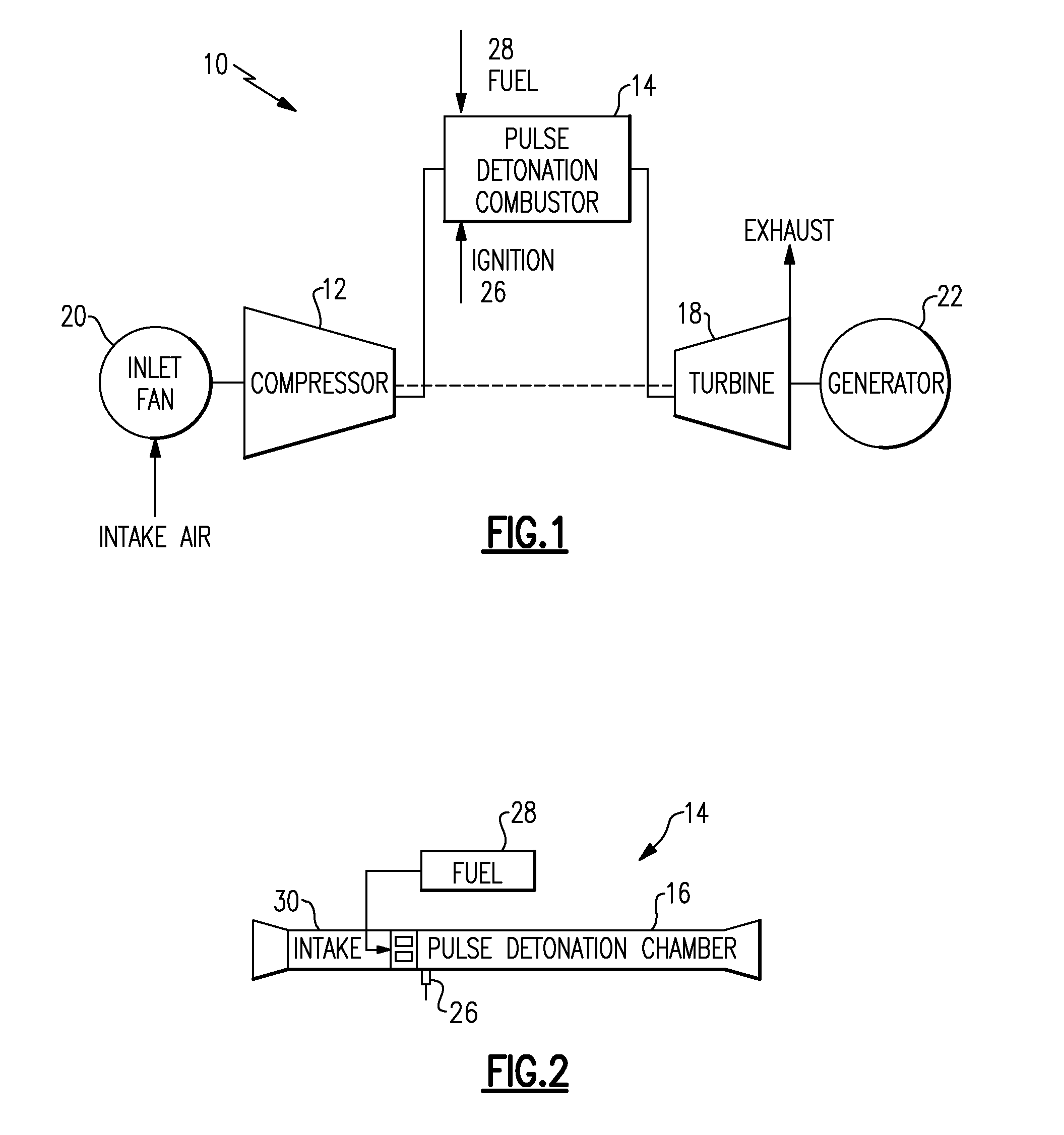
[0022]Referring now to FIGS. 1 and 2, various pulse detonation engine systems 10 convert kinetic and thermal energy of the exhausting combustion products into motive power necessary for propulsion and / or generating electric power. Illustrated in FIG. 1 is an exemplary embodiment of a pulse detonation combustor 14 in a pulse detonation turbine engine concept 10. Illustrated in FIG. 2 is an exemplary embodiment of a pulse detonation combustor 14 in a pure supersonic propulsion vehicle. The pulse detonation combustor 14, shown in FIG. 1 or FIG. 2, includes a detonation chamber 16 having an oxidizer supply section (e.g., an air intake) 30 for feeding an oxidizer (e.g., oxidant such as air) into the detonation chamber 16, a fuel supply section (e.g., a fuel valve) 28 for feeding a fuel into the detonation chamber 16, and an igniter (for instance, a spark plug) 26 by which a mixture of oxidizer combined with the fuel in the detonation chamber 16 is ignited.

[0023]In exemplary embodiments, ...


PUM


Abstract

A detonation chamber for a pulse detonation combustor including: a plurality of duplex tab obstacles disposed on at least a portion of an inner surface of the detonation chamber wherein the plurality of duplex tab obstacles enhance a turbulence of a fluid flow through the detonation chamber.

Description

BACKGROUND[0001]The present disclosure generally relates to cyclic pulsed detonation combustors (PDCs) and more particularly, the enhanced mixing and turbulence levels of the fuel-air mixture and flame kernel in order to promote the deflagration-to-detonation transition (DDT) process.[0002]In a generalized pulse detonation combustor, fuel and oxidizer (e.g., oxygen-containing gas such as air) are admitted to an elongated combustion chamber at an upstream inlet end. An igniter is used to initiate this combustion process. Following a successful transition to detonation, a detonation wave propagates toward the outlet at supersonic speed causing substantial combustion of the fuel / air mixture before the mixture can be substantially driven from the outlet. The result of the combustion is to rapidly elevate pressure within the combustor before substantial gas can escape through the combustor exit. The effect of this inertial confinement is to produce near constant volume combustion. Such d...

Claims


Application Information

Patent Timeline
Patent Type & Authority Applications(United States)
IPC IPC(8): F23R7/00F02K7/075
CPCF23C15/00F23R7/00F23R3/16F23M9/06
Inventor GUTMARK, EPHRAIM JEFFGLASER, AARON JEROMERASHEED, ADAM
Owner GENERAL ELECTRIC CO
Why Eureka
Try Eureka