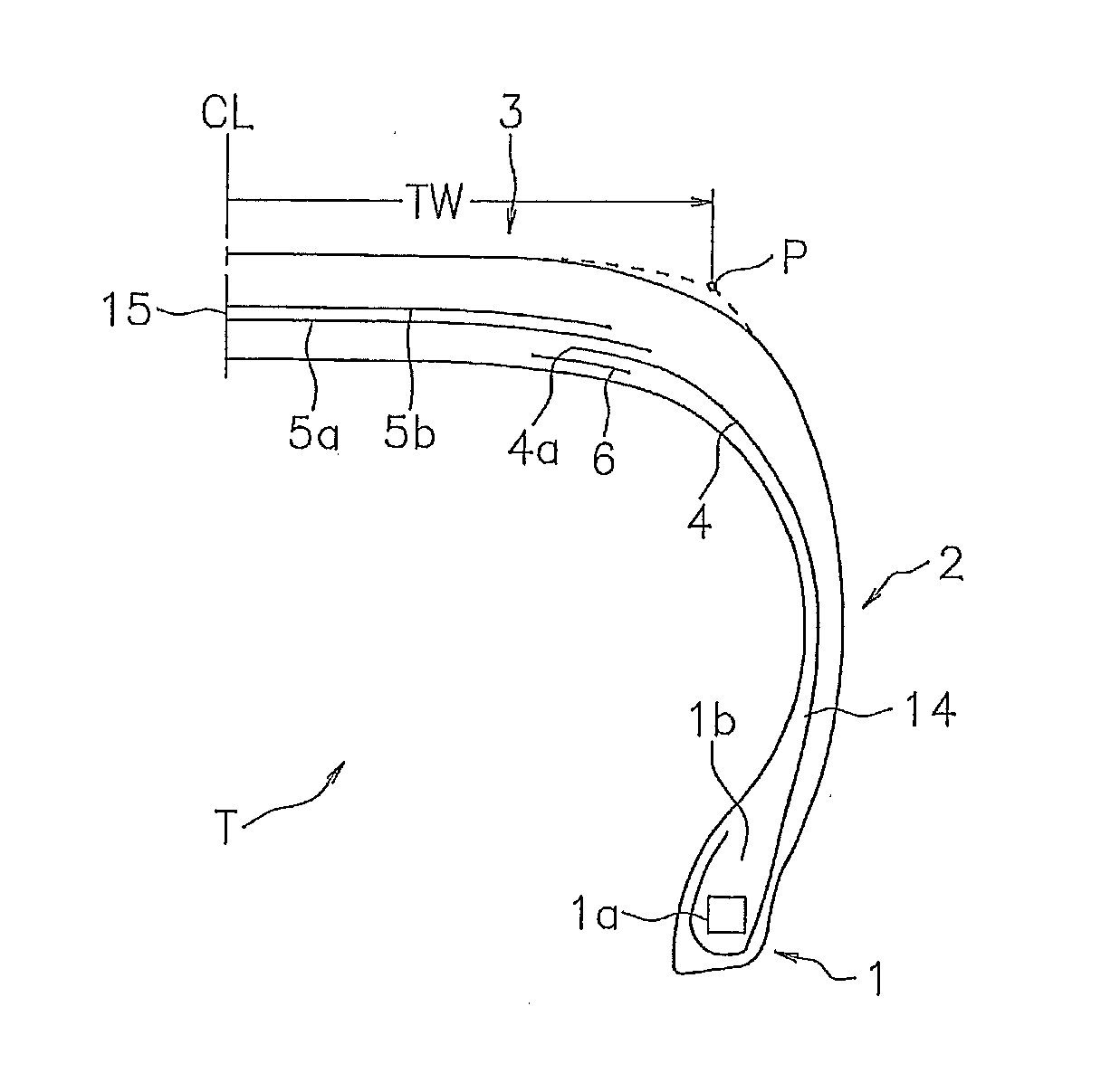
Pneumatic tire

a technology of pneumatic tires and cross-sectional tubes, which is applied in the direction of wheels, vehicle components, transportation and packaging, etc., can solve the problems of insufficient mass difference between shoulder regions and center regions, lack of effect of lowering high-frequency road noise, and insufficient suppression of vibration, so as to reduce high-frequency road noise, suppress vibration in the cross-section, and effectually suppress the effect of vibration

Inactive Publication Date: 2012-03-01
TOYO TIRE & RUBBER CO LTD
View PDF6 Cites 3 Cited by
  • Summary
  • Abstract
  • Description
  • Claims
  • Application Information

AI Technical Summary

Benefits of technology

[0009]In the pneumatic tire according to the present invention, since the division width of the carcass ply is equal to or more than 35% of the maximum width of the belt ply, the division end portion of the carcass ply is arranged near the end portion of the belt ply, and the auxiliary ply overlaps with the carcass ply in the inner peripheral side of the end portion of the belt ply, the mass difference is provided between the shoulder region and the center region, in cooperation with the division structure of the carcass ply. Further, since the auxiliary ply is formed by arranging the reinforcement cord extending at the angle within the range of ±20 degrees with respect to the tire width direction, it is possible to effectively suppress the vibration in the cross section higher order mode of the tire so as to reduce the high-frequency road noise in the vicinity of 1 kHz.
[0010]In the present invention, it is preferable that the auxiliary ply overlaps in the inner peripheral side of the carcass ply. Accordingly, the internal pressure of the tire tends to act on the auxiliary ply, and it is possible to satisfactorily suppress the vibration in the cross section higher order mode of the tire so as to enhance the reducing effect of the high-frequency road noise.
[0011]In the present invention, it is preferable that the auxiliary ply is divided in the tire width direction at the tread portion, and a division width of the auxiliary ply is smaller than the division width of the carcass ply. According to the structure mentioned above, it is possible to more securely lower the mass of the center region of the tire so as to improve the reducing effect of the high-frequency road noise. In addition, since the auxiliary ply extends outward to the inner side in the tire width direction than the division end portion of the carcass ply, the mass is gradually lowered from the shoulder region to the center region, and it is possible to avoid a rapid mass change.
[0012]In the present invention, it is preferable that the reinforcement cords extend so as to be inclined with respect to the tire width direction, and the carcass cord constructing the carcass ply extends so as to be inclined with respect to the tire width direction in such a manner as to intersect inversely to the reinforcement cord in a portion overlapping with the auxiliary ply. According to the structure mentioned above, the rigidity in the shoulder region of the tire becomes higher, and the high-frequency road noise in the vicinity of 1 kHz is effectively reduced.
[0013]In the present invention, it is preferable that a mass per unit width of the auxiliary ply is smaller than a mass per unit width of the carcass ply. In this case as well, the mass difference is provided between the shoulder region and the center region of the tire, and it is possible to obtain the lowering effect of the high-frequency road noise in the vicinity of 1 kHz.

Problems solved by technology

In a pneumatic tire described in Japanese Unexamined Patent Publication Nos. 10-157408 and 2007-283962, a carcass ply is divided at a tread portion for the purpose of improving durability, however, a sufficient mass difference cannot be provided between a shoulder region and a center region even by simply dividing the carcass ply, and an effect of lowering a high-frequency road noise is lacking.
Further, in these documents, a reinforcement layer is additionally lapped over a division end portion of the carcass ply, however, since the reinforcement layer is formed by cords extending in a tire circumferential direction, it is not sufficient for suppressing a vibration in a cross section higher order mode, and also lacks the lowering effect of the high-frequency road noise.

Method used


Image

  • Pneumatic tire
  • Pneumatic tire
  • Pneumatic tire

Examples


example

[0039]In order to specifically show the structure and the effect of the present invention, noise performance with regard to the high-frequency road noise in the vicinity of 1 kHz was evaluated, which will be described below. In this performance evaluation, a test tire (tire size 225 / 45R17) was installed to a test vehicle (2.5 L FR vehicle, two persons ride) while setting a pneumatic pressure to 220 kPa (front wheel) / 260 kPa (rear wheel) and setting a used rim to 17×8−JJ, and a road noise level (630 to 1.6 kHz) at the time of traveling at a speed 100 km / h on a road noise road of a test course was measured by using a microphone.

Comparative Examples 1 and 2

[0040]In the tire structure in FIG. 1, Comparative Example 1 was set to a structure in which the carcass ply was not divided, but was connected at the tread portion and the auxiliary ply was not provided. Further, in the tire structure in FIG. 1, Comparative Example 2 was set to a structure in which the ply was arranged as shown in ...

examples 1 to 3

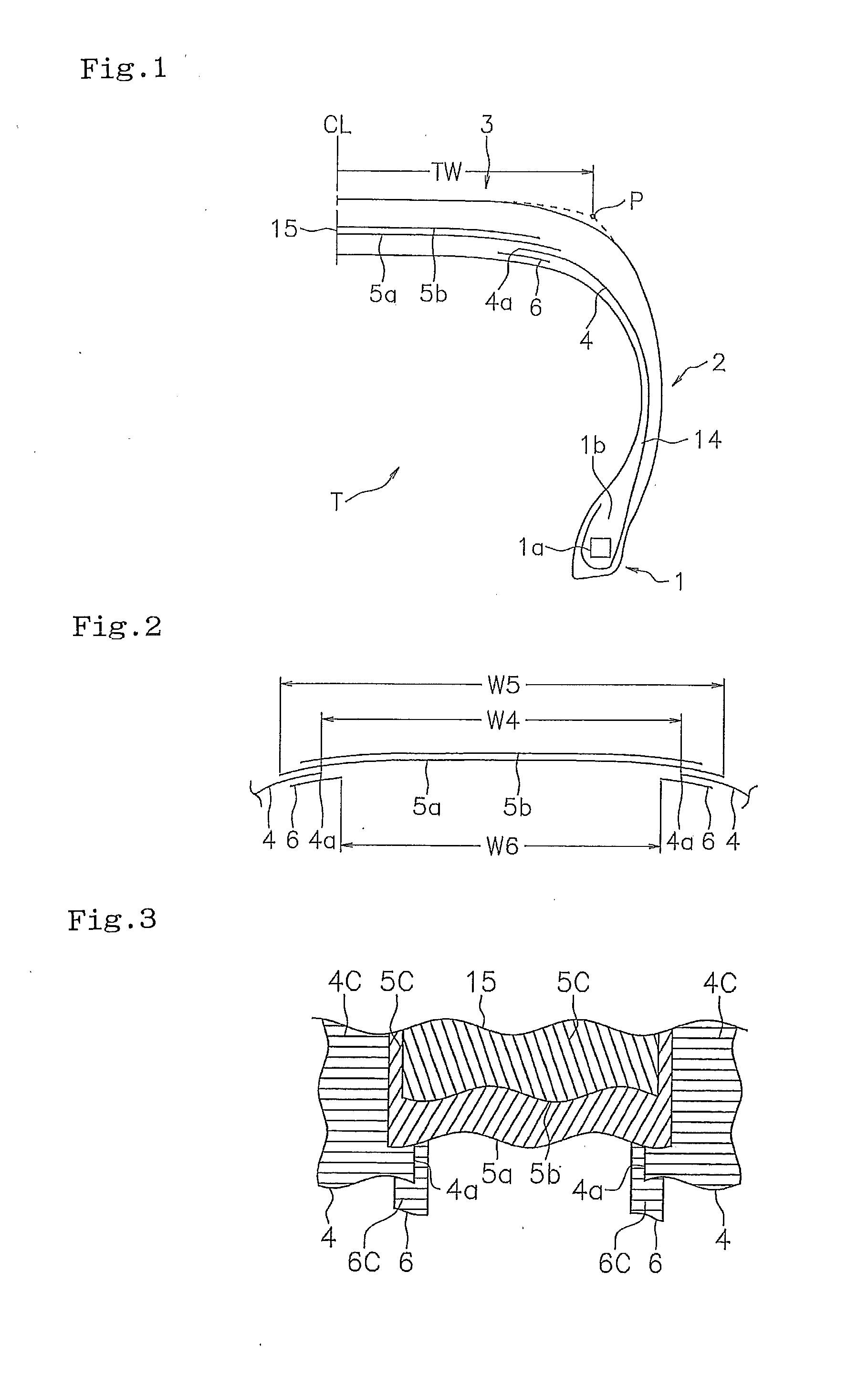
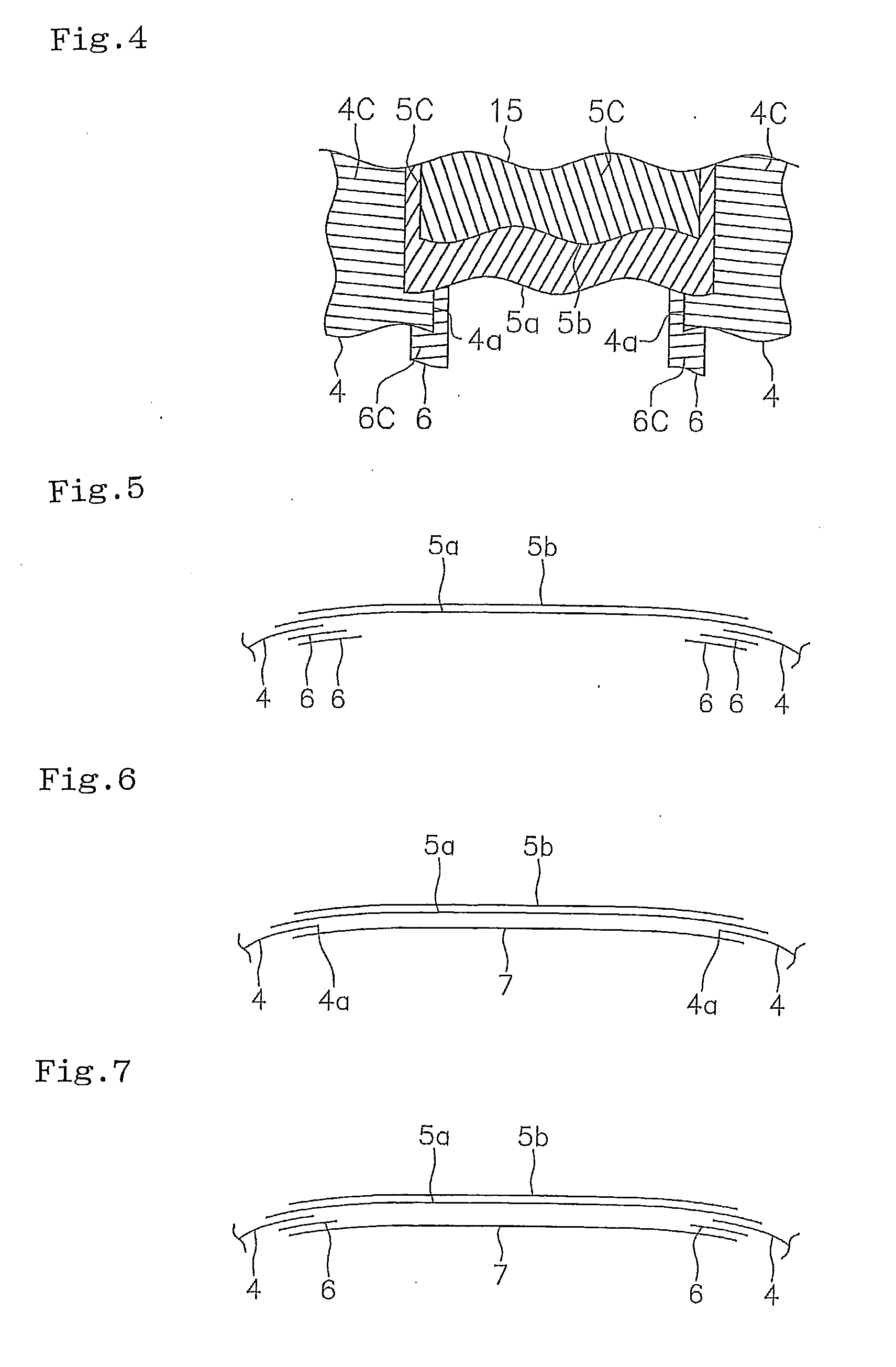
[0041]In the tire structure in FIG. 1, Example 1 was set to a structure in which the ply was arranged as shown in FIG. 2, Example 2 was set to a structure in which the ply was arranged as shown in FIG. 6, and Example 3 was set to a structure in which the ply was arranged as shown in FIG. 5. Results of the evaluation are shown in Table 1.

TABLE 1ComparativeComparativeExample 1Example 2Example 1Example 2Example 3Carcass plyDivisionAbsencePresencePresencePresencePresenceThickness (mm)  1.1  1.1  1.1  1.1  1.1Auxiliary plyDivision—PresencePresenceAbsencePresenceThickness (mm)—  0.9  0.9  0.9  0.9Angle (*1)—90°0°0°0°Reinforcement cord—PolyesterPolyesterPolyesterPolyesterNumber— 11 1 2ShapeFIG. 2FIG. 6FIG. 5Width W5 (mm)200200200200200Width W4 (mm)—100100100100Width W6 (mm)— 80 80 80 80W4 / W5—  50%  50%  50%  50%W6 / W4—  80%  80%  80%  80%Mass of position (*2)Shoulder100106106106115Center107 99 96102 96Center / shoulder107 93 91 94 83Road noise level (dB)0 (reference) −0.3 −1.2 −0.8 −1.3(*1): ...


PUM


Abstract

A pneumatic tire has a belt ply buried in a tread portion and a carcass ply running into an inner peripheral side of an end portion of the belt ply from a pair of bead portions. The carcass ply was divided in a tire width direction at the tread portion. A division width of the carcass ply is equal to or more than 35% of a maximum width of the belt ply. An auxiliary ply formed by reinforcement cords extending at an angle within a range of ±20 degrees with respect to the tire width direction is arranged in such a manner as to overlap with the carcass ply in an inner peripheral side of the end portion of the belt ply and extend out to an inner side in the tire width direction than the division end portion of the carcass ply.

Description

BACKGROUND OF THE INVENTION[0001]1. Field of the Invention[0002]The present invention relates to a pneumatic tire structured such that it can reduce a high-frequency road noise in the vicinity of 1 kHz at the time of traveling.[0003]2. Description of the Related Art[0004]In recent years, there is a tendency that a request for noise reduction of a tire is enhanced in accordance with a high class and high quality of a vehicle, and it is particularly important to lower a road noise which is generated by a transmission of a vibration caused by an unevenness of a road surface applied to a tread portion.[0005]The present inventor has devoted himself to study of the road noise, accordingly has found a cross section higher order vibration mode affecting a high-frequency road noise in the vicinity of 1 kHz, by an analysis and an experiment, and has found such information that it is possible to suppress a vibration of a cross section higher order mode of a whole of the tire so as to effective...

Claims


Application Information

Patent Timeline
Patent Type & Authority Applications(United States)
IPC IPC(8): B60C9/02
CPCB60C9/28B60C2009/2016B60C2009/0215Y10T152/10855B60C9/0207B60C2009/1892B60C2009/2038
Inventor SEGAWA, MASAHIRO
Owner TOYO TIRE & RUBBER CO LTD
Why Eureka
Try Eureka