Pusher Unit of Glue Applicator

Inactive Publication Date: 2012-03-01
YEU CHYUAN INDAL
View PDF7 Cites 7 Cited by
  • Summary
  • Abstract
  • Description
  • Claims
  • Application Information

AI Technical Summary

Benefits of technology

[0011]Thereby, the feeding unit of the present invention is composed of merely the sliding seat, the gripper and the trigger, so it is simpler in structure, easy to assemble, and more effective to produce. Meanwhile, sliding

Problems solved by technology

However, the gun-like glue applicator is less controllable for accurate placement of the glue.
Since the entire structure involves a relatively large number of complex components, assembly of the existing glue applicator is difficult and inconvenient, which significantly affects the efficiency and costs of production.
In addition, feeding the glue stick relies on the l

Method used


Image

  • Pusher Unit of Glue Applicator
  • Pusher Unit of Glue Applicator
  • Pusher Unit of Glue Applicator

Examples


Embodiment Construction

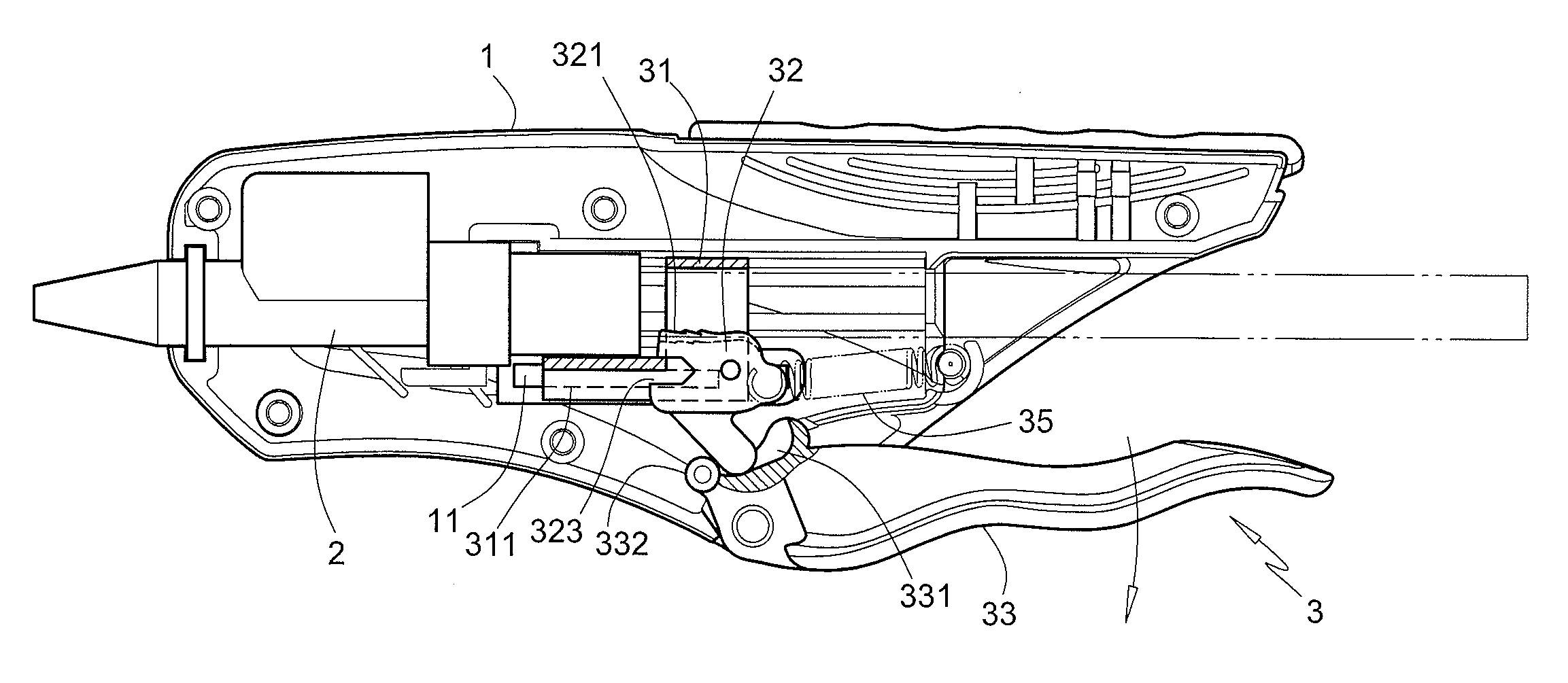
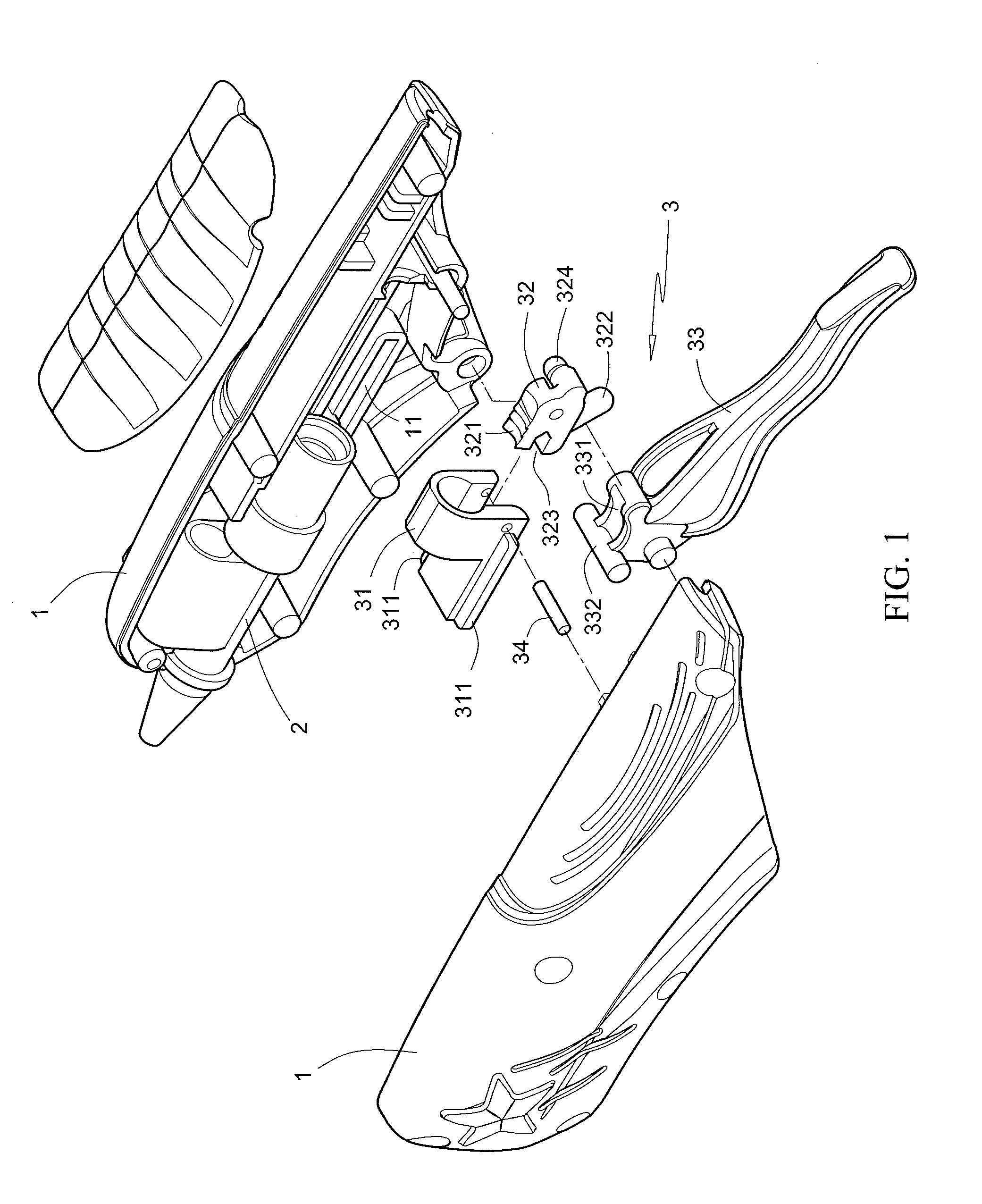
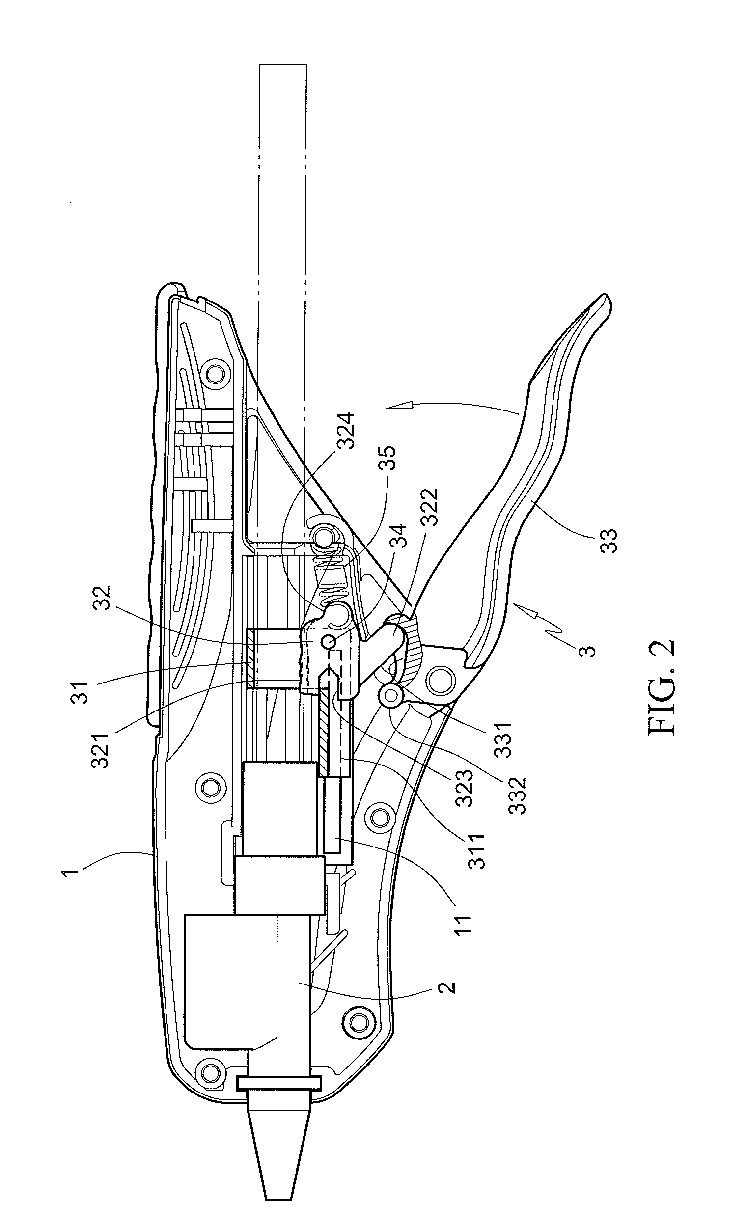
[0016]Please refer to FIGS. 1 and 2. The present invention is directed to a glue applicator that comprises a body 1 receiving a heat chamber 2 at a front end thereof, and a feeding unit 3 for driving a glue stick into the heat chamber 2. The feeding unit 3 further includes a sliding seat 31 that allows the glue stick to pass therethrough and is bilaterally provided with wing portions 311, so that the wing portions 311 are configured to slide along sliding guides 11 provided on the body 1. At a lower rear portion of the sliding seat 31, a pivotal shaft 34 positions a swingable gripper 32. The gripper 32 has its front end provided with a notch 323 fitting the sliding seat 31, with its top surface provided with a toothed anti-slip engaging surface 321, with its lower end provided with a projecting portion 322 extending slantwise downward, and with its one lateral provided with a holding portion 324.

[0017]Moreover, the feeding unit 3 further comprises a trigger 33 pivotally fixed to the...


PUM


Abstract

An improvement to a feeding unit of a glue applicator is disclosed. The glue applicator includes a body having a heat chamber and a feeding unit for pushing a glue stick into the heat chamber. The feeding unit includes a sliding seat sliding in the body and allowing the glue stick to pass therethrough. A gripper pivotally fixed to the sliding seat is rotatable to engage with the glue stick, and has a projecting portion extending slantwise downward. A trigger pivotally fixed to the body automatically returns to an initial position thereof, and has a top thereof provided with a recess for receiving the projecting portion of the gripper. When the trigger is transversely drawn toward the body, the recess pushes the gripper to engage the glue stick, so the glue stick is advanced together with the sliding seat, causing the glue stick to be fed into the heat chamber.

Description

FIELD OF THE INVENTION[0001]The present invention relates to a mechanical improvement made to a feeding unit of a glue applicator. More particularly, the present invention provides a feeding unit for drawing and thus feeding a glue stick installed therein. The feeding unit is composed of reduced number of components and allows a more effort-saving operation.BACKGROUND OF THE INVENTION[0002]As generally known, a glue applicator is used to heat a glue stick and to apply the melted glue for adhesion. Such a glue applicator is typically designed with a gun-like shape. However, the gun-like glue applicator is less controllable for accurate placement of the glue. Therefore, a glue applicator featuring for being easily held has been developed, as disclosed in U.S. Pat. No. 6,820,768.The patented glue applicator primarily has a body, a cavity extending along the longitudinal axis of the body, a heat chamber received in and extending parallel to the cavity so as to receive a glue stick placi...

Claims


Application Information

Patent Timeline
IPC IPC(8): B05C17/01B67D7/80B65H20/00
CPCB05C17/0053
Inventor YUNG-KUAN, HUANG
Owner YEU CHYUAN INDAL
Why Eureka
Try Eureka