Method for manufacturing a gasket with an encapsulated metal band

a technology of metal band and gasket, which is applied in the field of manufacturing an improved reinforced gasket, can solve the problems of defeating the purpose of the gasket, not revealing how, and unsuitable gaskets made entirely from elastomeric materials, etc., and achieves the effects of reducing the diameter of the metal band, reducing the amount of metal used, and greatly simplifying the mold used to make the gask

Inactive Publication Date: 2012-03-01
MAXSEAL
View PDF12 Cites 18 Cited by
  • Summary
  • Abstract
  • Description
  • Claims
  • Application Information

AI Technical Summary

Benefits of technology

[0010]The metal band of the present invention incorporates a lateral support system in the form of circumferentially-spaced raised projections. Dimples are stamped into the inner surface of the band, forming raised projections on the outer surface of the metal band. These projections cause the metal band to be positively separated from the cavity wall of the mold when the metal band is positioned therein. As a result, the diameter of the metal band used is decreased, reducing the amount of metal used in making the reinforcing band for a gasket.
[0011]The mold used to make the gasket is greatly simplified, without the need for radial or axial support pins requiring adjustment and maintenance. With fewer pins, the mold is easier to clean. Further, its raised projections allow the metal band to be positioned easily and accurately within the cavity, reducing accidental displacement during mold closure, thus decreasing mold damage and the production of defective gaskets.
[0012]Because the raised projections are an integral part of the metal band, complete encapsulation of the metal band is accomplished. Further, the shape of the projections increases the contact area of the metal band, improving adhesion of the elastomer to the metal band.
[0013]The metal band can be stamped with dimples in different patterns around the circumference of the metal band; for instance, a metal band with a large diameter may be stamped to form raised projections in patterns that improve positioning of the metal band in the mold cavity.

Problems solved by technology

It soon became apparent that gaskets made entirely from elastomeric materials were unsuitable for pressure applications.
However, because the rubber layer 6 was not molded with the gasket 5, it tended to peel away when the gasket was being installed during belling of the pipe, or during operation of the joint, thus defeating its purpose.
The patent does not disclose how the band is made, nor how the gasket is molded, but the gasket is not currently being manufactured.
In any event, after molding, the apex of the metal band is exposed around the outer circumference of the gasket, leading to the same problems described, supra.

Method used


Image

  • Method for manufacturing a gasket with an encapsulated metal band
  • Method for manufacturing a gasket with an encapsulated metal band
  • Method for manufacturing a gasket with an encapsulated metal band

Examples


Embodiment Construction

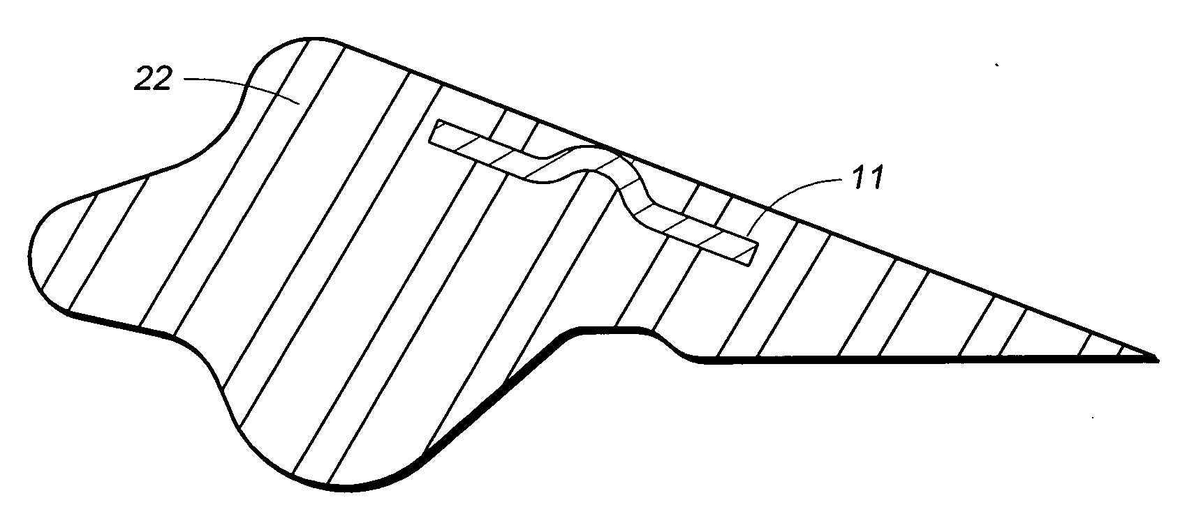
[0037]The present invention uses a slightly conical, hoop-shaped metal band 11, which has a pattern of dimples 12 formed in the inner surface 13 of the metal band 11, each dimple 12 forming a raised projection 14 on the outer face 15 of the metal band 11. The metal used to form the band 11 is typically steel which can be stamped in a die. The band can also be made from copper, brass, or another metal. The process for making the metal band 11 from steel is described in FIGS. 14A-C through FIG. 18, infra.

[0038]A gasket produced by injection molding can be reinforced using the metal band 11 of the present invention. As shown in FIG. 8, the metal band 11 is placed in the injection mold 16, with its lower edge resting against the tops of core support pins 17. The outer face 15 of the metal band 11 is spaced apart from the cavity wall 18 of the lower mold plate 19 by the raised projections 14 on the outer face 15 of the metal band 11.

[0039]As shown in FIG. 9, the upper mold plates 20, 21,...


PUM

PropertyMeasurementUnit
elastomericaaaaaaaaaa
circumferenceaaaaaaaaaa
lengthaaaaaaaaaa

Abstract

A method for manufacturing a gasket that is reinforced by a metal band, which is completely encapsulated within the elastomeric material of the gasket. The metal band is formed with spaced-apart dimples stamped into its inner surface, causing raised projections to form on the outer surface of the metal band. When the metal band is placed in a mold, the raised projections on its outer surface cause the metal band to be spaced apart from the inner wall of the mold. Elastomeric material is then injected into the mold and is able to completely encapsulate the metal band. The gasket is cured and then removed from the mold.

Description

FIELD OF THE INVENTION[0001]The present invention relates to manufacturing an improved reinforced gasket for sealing pipe joints.BACKGROUND OF THE INVENTION[0002]Pipelines for conveying fluids can be made from a number of different materials, including plastic materials, such as polyvinyl chloride (PVC), and metals, such as steel, brass and aluminum. Each length of such pipe typically has a belled female end and a spigot male end. The joints between sections of pipe are sealed, typically with a gasket. PVC pipe systems have often relied on the “Rieber Joint,” which was developed in the early 1970's by Rieber & Son of Bergen, Norway, to seal the connections. The Rieber Joint has an elastomeric gasket inserted into a groove on the inside of the belled end of a piece of the PVC pipe as the female end is being formed.[0003]It soon became apparent that gaskets made entirely from elastomeric materials were unsuitable for pressure applications. The obvious solution was incorporating a meta...

Claims


Application Information

Patent Timeline
Patent Type & Authority Applications(United States)
IPC IPC(8): B29C45/14
CPCB29C45/14065B29C45/1459B29C2045/14131B29C2045/14122F16J15/121F16L21/03B29C45/14819B29L2031/265
Inventor GUZOWSKI, SAMUEL
Owner MAXSEAL
Why Eureka
Try Eureka