Steering support member structure

Inactive Publication Date: 2012-03-01
SUZUKI MOTOR CO LTD
View PDF6 Cites 16 Cited by
  • Summary
  • Abstract
  • Description
  • Claims
  • Application Information

AI Technical Summary

Benefits of technology

[0021]Thus, in the structure of the present invention, two edge parts of the brace and two members of the steering bracket are overlappingly assembled into a lattice form for two support members: the first and second support members, so that the opposing both edge parts of the C-shaped or U-Shaped brace serve to suppress the vibration against the fore-and-aft vibration of the steering support member in the above-described vibration mode 1, and particularly the edge part on the middle side of the brace is close to the antinode of vibration and therefore is effective in suppressing the motion. Moreover, in the structure of the present invention, the opposing both edge parts of the C-shaped or U-shape brace serve to suppress the vibration against the fore-and-aft vibration of the steering support member in the above-described vibration mode 2, as well as have a reduction effect on the rotational component in the horizontal surface around the middle node. The amplitude near the C-shaped or U-shaped brace is reduced in motion, since vibrations of the nodes at both ends and the middle have opposite phases for the fore-and-aft motion of the whole structure, and thus the two amplitudes are neutralized in the vicinity of the outer edge part. Furthermore, the structure of the present invention allows the rigidity of the entire steering support member to be increased by the brace and the steering bracket which are disposed so as to be partially overlapped. Moreover, when the vibration mode is different between the first and second support members, since it becomes possible to suppress the antinode of the vibration by fine adjusting the position of the brace and the steering bracket, or selecting the rigidity of the brace, it is possible to set an optimal vibration mode in accordance with vehicle types.
[0022]Moreover, in the structure of the present invention, since there is constructed between the opposing edge parts of the C-shaped or U-shaped brace, a pipe member which is disposed in parallel with the first support member, and connects with the opposing edge parts at an intermediate position in the front-rear direction between the first support member and the base part of the brace, the pipe member acts like a “prop or drawb

Problems solved by technology

If the peripheral portions of such a steering support member have low rigidity, there is a concern that vibrations from the body suspension, particularly vibrations from the engine during idling may be transferred to the steering, and such vibrations may give discomfort such as by propagating to the driver or causing vehicle interior noise, as well as that vibrations of equipment may cause squeaking.
Moreover, when a load is applied from the front of vehicle body, the upper part of the dash panel and the cowl panel may deform, intruding into the vehicle interior, and thereby the steering support member may deform toward the rear of the vehicle body, resulting in a problem of the retreat of the steering wheel.
Particularly problematic are a fore-and-aft (from diagonally to the upper front to diagonally to the lower rear) vibration mode in which the antinode of vibration curve is located at the middle in vehicle-body width direction of the steering support member, and a fore-and-aft vibration mode in which the node of vibration curve is located at both ends and the middle of the steering support member.
Since these vibration modes inevitably take place in a

Method used


Image

  • Steering support member structure
  • Steering support member structure
  • Steering support member structure

Examples


Example

[0029]Hereafter, the present invention will be described in detail based on the illustrated embodiments.

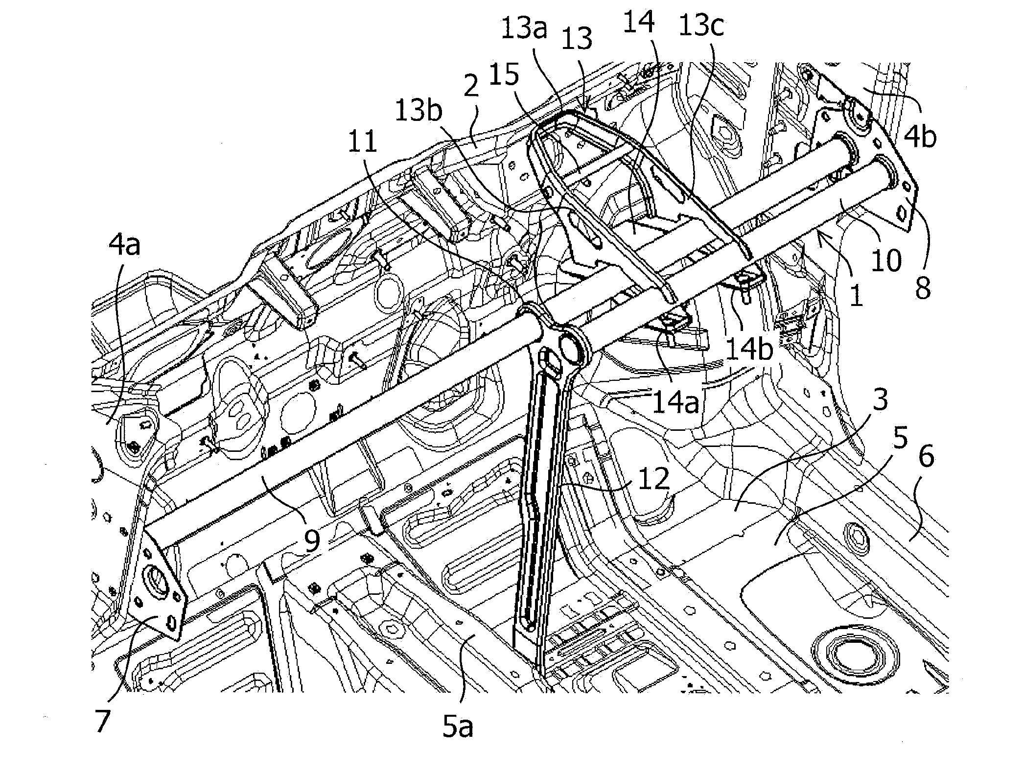
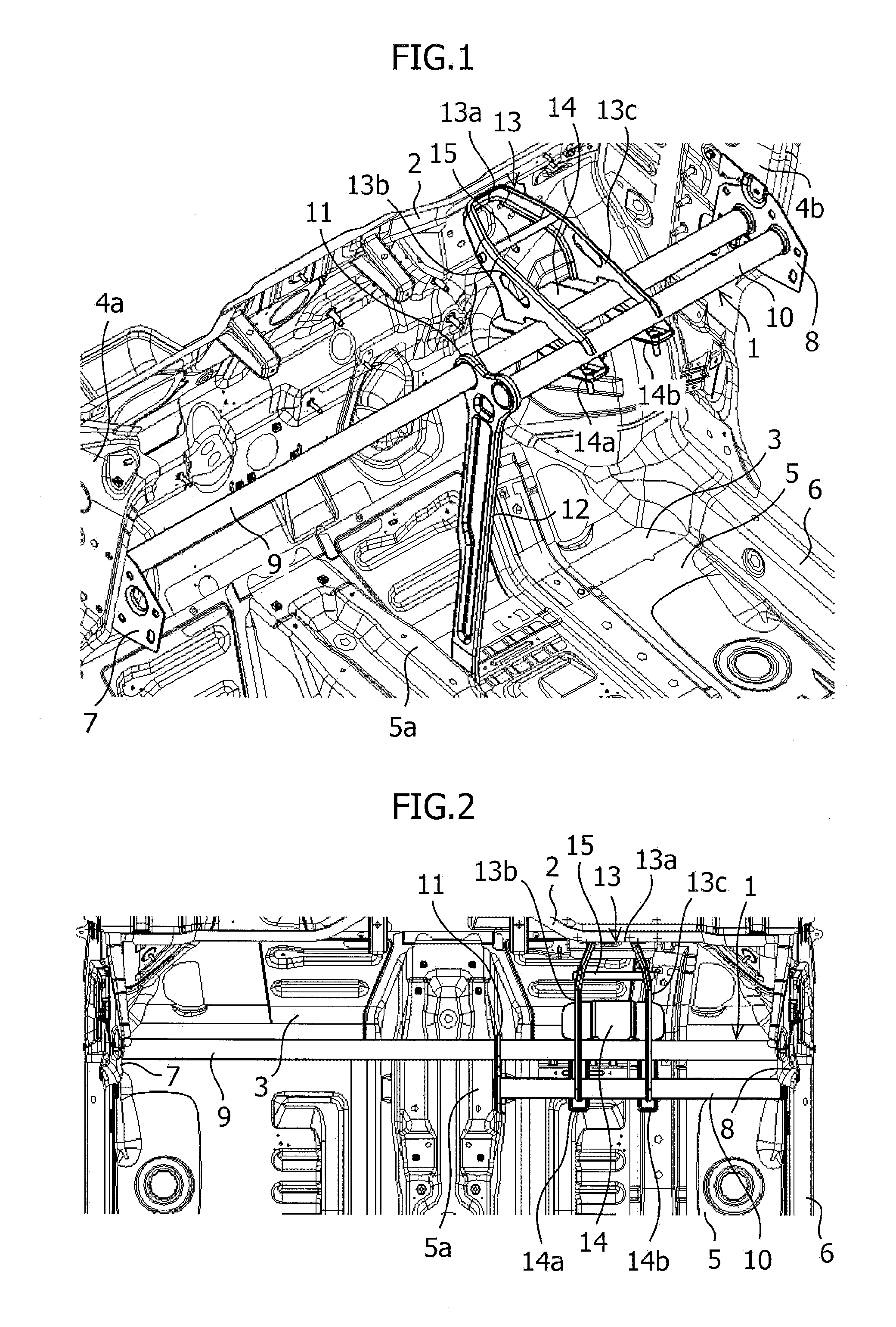
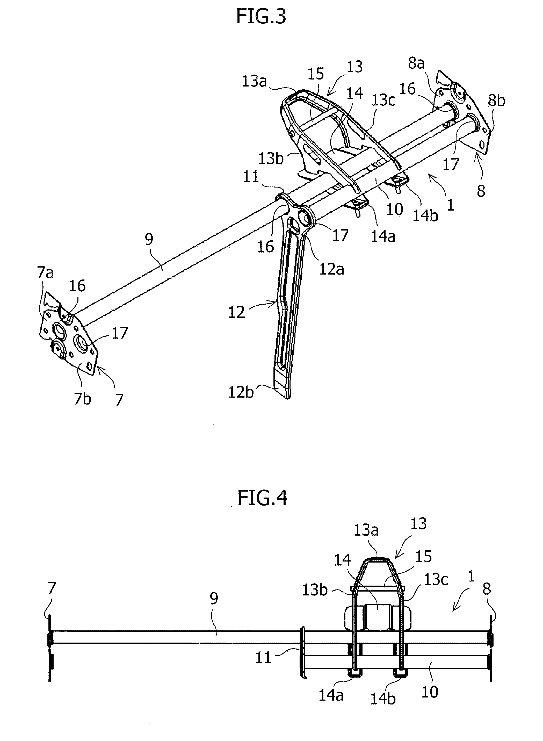
[0030]FIG. 1 is a perspective view of the vehicle interior of a motor vehicle to which the structure of a steering support member relating to an embodiment of the present invention is applied; FIG. 2 is a plan view of the vehicle interior of the motor vehicle of FIG. 1; FIG. 3 is a perspective view of the structure of the steering support member of the present embodiment; and FIG. 4 is a plan view of the structure of the steering support member of FIG. 3.

[0031]A steering support member 1 which is a rigid member extending in the vehicle-body width direction is arranged in the upper part of the front side of the vehicle interior of a motor vehicle as shown in FIGS. 1 and 2. This steering support member 1 is disposed inside an instrument panel (not shown), which is a large scale resin molded component, and in which various pieces of equipment are installed and support the instrument ...


PUM


Abstract

A structure of a steering support member, which enables the reduction of vehicle interior noise and steering vibration by suppressing the fore-and-aft vibration of the steering support member by means of a C-shaped or U-shaped brace and by increasing the rigidity of the steering support member in the front of the driver seat side, and enables the setting of a vibration mode in accordance with vehicle types by fine adjusting the positions of the brace and a steering bracket and by selecting the rigidity of the brace.

Description

CROSS-REFERENCE TO RELATED APPLICATIONS[0001]The present application claims the benefit of Japanese Patent Application No. 2010-188256, filed Aug. 25, 2010, the disclosure of which is hereby incorporated by reference herein.FIELD OF THE INVENTION[0002]The present invention relates to the structure of a steering support member which is constructed across the width of a vehicle body within an instrument panel of a motor vehicle to support the steering column, etc.DESCRIPTION OF RELATED ART[0003]Conventionally, inside an instrument panel of a motor vehicle, a steering support member, which is a rigid member for supporting the steering column etc., is constructed across the width of the vehicle body. The steering support member is attached at both ends in the vehicle-body width direction to left and right dash side panels (pillars), and supports the steering column via a steering bracket on the driver seat side, and an instrument panel is mounted thereon, with heavy components such as m...

Claims


Application Information

Patent Timeline
IPC IPC(8): B62D1/16B62D25/14
CPCB62D25/145
Inventor ATSUMI, RYO
Owner SUZUKI MOTOR CO LTD
Why Eureka
Try Eureka