Method for detecting icing at an angle-resolving radar sensor in a driver assistance system for motor vehicles

Active Publication Date: 2012-03-01
ROBERT BOSCH GMBH
View PDF5 Cites 6 Cited by
  • Summary
  • Abstract
  • Description
  • Claims
  • Application Information

AI Technical Summary

Benefits of technology

[0010]An object of the present invention is to provide a method that permits impairment of t

Problems solved by technology

A film of water or a coating of dirt on the lens or radome may, however, cause the radar radiation to be attenuated to such a great extent that the object peaks no longer have a sufficient signal-to-noise ratio and therefore reliable object detection is no longer possible.
With that conventional method, it is not possible, however, to detect a layer of ice on the radar lens or radome, since a layer of ice generally does not lead to significant attenuation of the radar signal.
However, since such a layer of ice has a refractive index that is different from the refractive index of air, it may lead,

Method used


Image

  • Method for detecting icing at an angle-resolving radar sensor in a driver assistance system for motor vehicles
  • Method for detecting icing at an angle-resolving radar sensor in a driver assistance system for motor vehicles
  • Method for detecting icing at an angle-resolving radar sensor in a driver assistance system for motor vehicles

Examples


Embodiment Construction

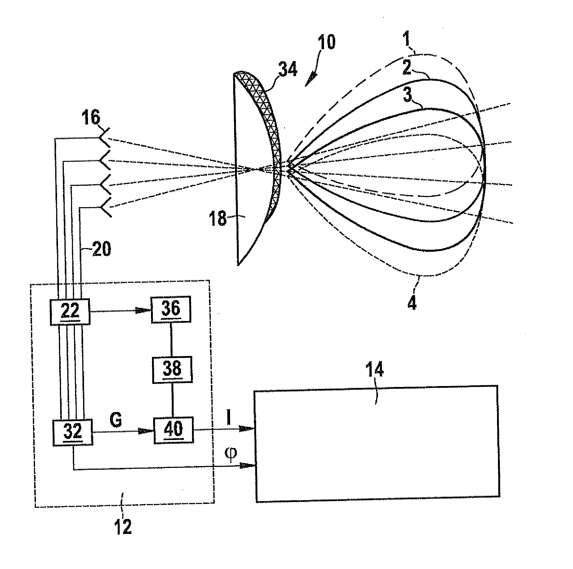
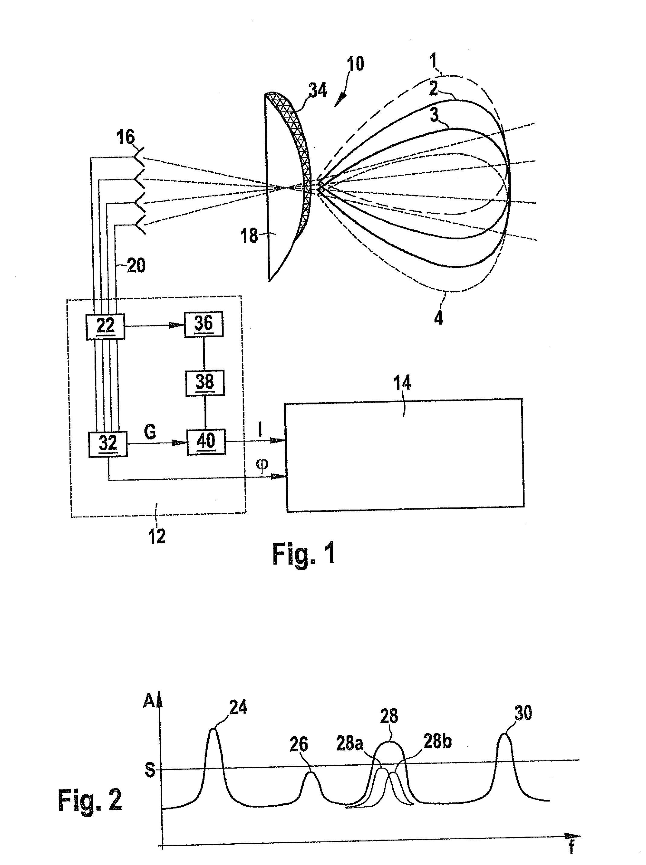
[0020]The driver assistance system shown in FIG. 1, for example an ACC system, includes a radar sensor 10, of which only the main components that are used in connection with the present invention are illustrated, a first evaluation stage 12 and a second evaluation stage 14.

[0021]Radar sensor 10 has four antenna elements 16, which are disposed in front of a common lens 18. When radar sensor 10 is installed in a motor vehicle, not shown, the optical axis of lens 18 points, for example, in the longitudinal direction of the vehicle, and antenna elements 16 are disposed in laterally offset relationship to one another on a horizontal line. The emitted radar radiation is concentrated by lens 18, and the received radar echoes are again focused onto antenna elements 16. The angular distribution of the emitted radiation and the sensitivity are symbolized in FIG. 1 by radar lobes 1-4, one lobe for each antenna element. Owing to the offset relationship of the antenna elements, the axes of the i...


PUM


Abstract

A method for detecting icing at an angle-resolving radar sensor in a driver assistance system for motor vehicles, in which signals of a plurality of antenna elements each having a specific angle characteristic are compared with the corresponding angle characteristics, and the azimuth angle of a located object is determined on the basis of an angle fit quality which indicates how well the signals of the antenna elements correspond to the angle characteristics for a given azimuth angle, wherein an indicator for icing is formed which is a monotonically falling function of the angle fit qualities of the located objects, with objects having a low signal-to-noise ratio being included in the indicator at the most with a reduced weighting.

Description

FIELD OF THE INVENTION[0001]The present invention relates to a method for detecting icing at an angle-resolving radar sensor in a driver assistance system for motor vehicles, in which signals from a plurality of antenna elements each having a specific angle characteristic are compared with the corresponding angle characteristics, and the azimuth angle of a located object is determined on the basis of an angle fit quality which indicates how well the signals of the antenna elements correspond to the angle characteristics for a given azimuth angle.BACKGROUND INFORMATION[0002]Motor vehicles are increasingly being fitted with driver assistance systems, for example with so-called ACC (adaptive cruise control) systems, which allow the distance of the driver's own vehicle from a vehicle in front to be automatically regulated. To that end, the distances and azimuth angles and also the relative speeds of vehicles travelling in front are measured with the aid of the radar sensor, for example ...

Claims


Application Information

Patent Timeline
IPC IPC(8): G01R27/04G01S13/931
CPCG01S13/424G01S13/931G01S2007/4039G01S2013/9325G01S13/56G01S13/951G01S7/412G01S7/4039
Inventor HEILMANN, STEFANGROSS, VOLKERKUEHNLE, GOETZBECHLER, DIRK
Owner ROBERT BOSCH GMBH
Why Eureka
Try Eureka