First Embodiment
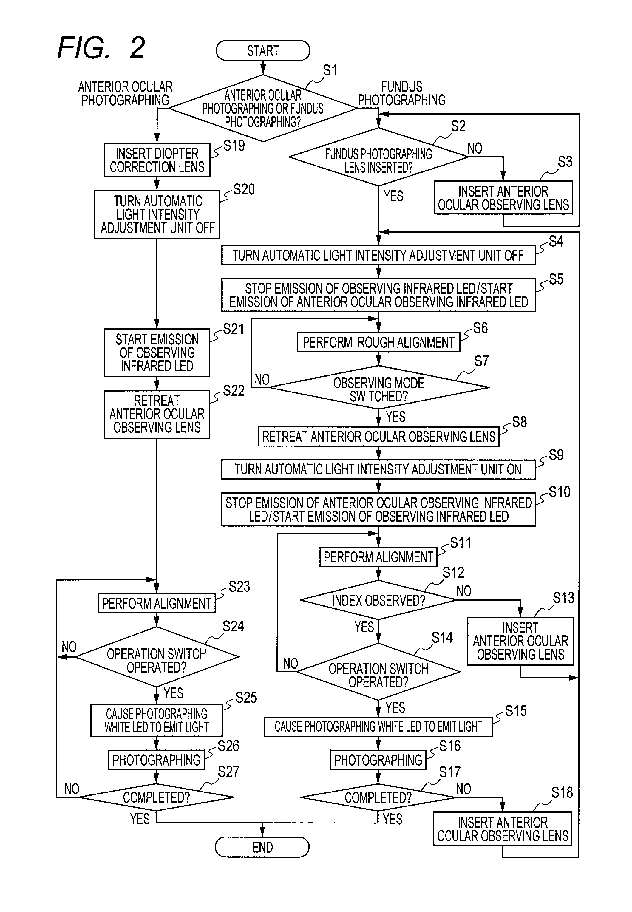
[0024]In the following, a fundus camera having a fundus mode, an anterior ocular observation mode, and an anterior ocular photographing mode is described as an example.
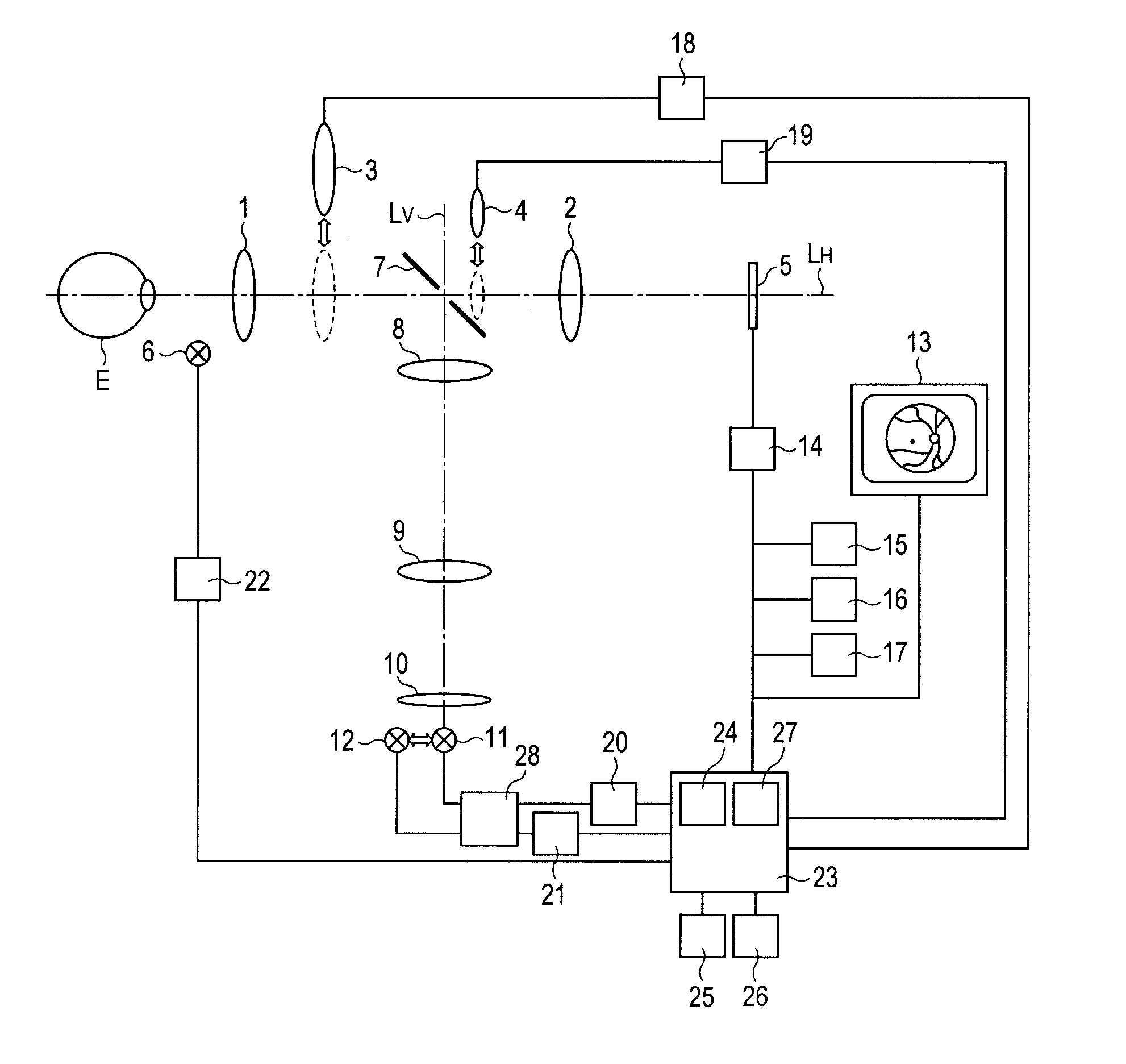
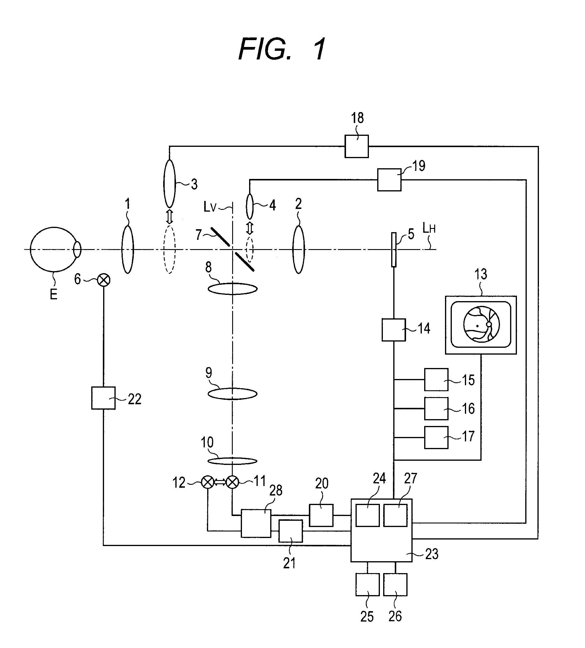
[0025]FIG. 1 is a configuration diagram according to a first embodiment in which the present invention is applied to the fundus camera.
[0026]An objective lens 1 is disposed to oppose an eye E to be inspected. On an optical axis (path) LH of the objective lens 1, there are provided an image-forming lens 2, an anterior ocular observing lens 3 that is insertable and retreatable to and from the optical axis LH, a diopter correction lens 4 that is similarly insertable and retreatable to and from the optical axis LH, and a photographing element 5 having sensitivity to visible light and infrared light. In addition, at a substantially peripheral portion of the objective lens 1, an anterior ocular illumination infrared LED 6 for irradiating the anterior ocular segment of the eye E to be inspected, in particular a peripheral region of the anterior ocular segment, is provided. Further, on the same optical axis LH, an perforated mirror 7 is diagonally provided.
[0027]The anterior ocular illumination infrared LED 6 works as an anterior ocular observation light source of the present invention, and emits anterior ocular observation light to illuminate mainly the anterior ocular segment of the eye E to be inspected.
[0028]The components from the objective lens 1 to the image-forming lens 2 together constitute an observation optical system. The observation optical system and the photographing element 5 together constitute an observing and photographing unit. The photographing element 5 receives light which is projected by an illumination unit to be described later and the like, namely reflected light which is reflected from the eye E to be inspected. The photographing element 5 then generates and outputs an image signal.
[0029]On an optical axis (path) LV of the perforated mirror 7 in a reflection direction, a lens 8, a lens 9, and a condenser lens 10 are provided. In addition, on the same optical axis LV, a photographing white LED 11 and an observing infrared LED 12 are provided so as to be switchable.
[0030]The components from the objective lens 1 to the condenser lens 10 together constitute an illumination optical system. The illumination optical system, the photographing white LED 11 as a photographing light source, and the observing infrared LED 12 as an observation light source together constitute the illumination unit. The photographing white LED 11 emits photographing light for photographing the eye E to be inspected to illuminate the eye E to be inspected. The observing infrared LED 12 emits observation light for observing the eye E to be inspected to illuminate the eye E to be inspected.
[0031]The above-mentioned observing and photographing unit and the illumination unit together constitute a fundus camera optical portion. The fundus camera optical portion is placed on a slide table (not shown), enabling alignment with the eye E to be inspected.
[0032]An output of the photographing element 5 is converted into a digital signal by an A/D converter element 14. The digital signal is stored in a memory 15 and also connected to a photometry value calculation unit 16. The memory 15 and the photometry value calculation unit 16 are both connected to a control unit (device) 23 for controlling the entire apparatus. The control unit 23 is connected to an image memory 25, and a still image imaged by the photographing element 5 is stored therein as a digital image.
[0033]The photographing element 5, the A/D converter element 14, the memory 15, and the photometry value calculation unit 16 as well as a monitor 13 for displaying an infrared observed image and a visible image which are imaged by the photographing element 5 and a photographing unit control portion 17 together constitute an photographing unit. In addition, the photographing unit is fixed to a housing of the fundus camera optical portion via a mount portion (not shown) in a detachable manner.
[0034]Movement of the fundus camera is controlled by the control device 23.
[0035]The anterior ocular observing lens 3 is inserted and retreated to and from the optical path LH by an anterior ocular observing lens control unit 18 connected to the control device 23. Further, whether or not the diopter correction lens 4 is present on the optical path LH is judged by a diopter correction lens position detection unit 19 connected to the control device 23.
[0036]The photographing white LED 11 and the observing infrared LED 12 are connected to a light source switching unit 28. Which of the light sources is to be disposed on the optical path LV is switched by the control unit 23.
[0037]A light intensity adjustment control unit 24 is controlled by the control device 23 and performs selection of a light source and selection of a calculation method. A light intensity calculation unit 27 as a calculation unit of the present invention calculates an emission intensity according to a photometry value obtained by the photometry value calculation unit 16 and the light source and the calculation method selected by the light intensity adjustment control unit 24. In other words, the light intensity calculation unit 27 is capable of switching the calculation contents, the calculation method, and the like according to a mode of the light intensity adjustment control unit 24 to be described later, and can be defined as including a calculation switching unit for performing the switching.
[0038]A photographing white LED light intensity control unit 20, an observing infrared LED light intensity control unit 21, and an anterior ocular observing infrared LED light intensity control unit 22 cause the photographing white LED 11, the observing infrared LED 12, and the anterior ocular illumination infrared LED 6 to emit light at the light intensities calculated by the light intensity calculation unit 27, respectively.
[0039]A photographing switch 26 is connected to the control device 23. When the photographing switch 26 is operated, the above-mentioned control unit causes the respective LEDs as the light source units to emit light at the calculated light intensities so that the observing and photographing unit images an image of the eye to be inspected, which is then recorded.
[0040]Next, an actual action of the fundus camera to which the present invention is applied when the automatic light intensity adjustment unit is enabled and used in the fundus mode while the automatic light intensity adjustment unit is disabled and not used in an anterior ocular mode that consists of the anterior ocular observation mode and the anterior ocular photographing mode is described.
[0041]FIG. 2 is a flowchart for photographing by the fundus camera according to the first embodiment.
[0042]In Step S1, which of the anterior ocular photographing and the fundus photographing of the eye to be inspected is to be performed is selected, that is, which of the anterior ocular mode and the fundus mode is to be executed is selected.
[0043]In the beginning, an action when the fundus photographing is performed is described.
[0044]In Step S2, it is judged whether or not the anterior ocular observing lens 3 is inserted onto the 3 is not inserted onto the optical path LH, the processing proceeds to Step S3, in which the anterior ocular observing lens control unit 18 inserts the anterior ocular observing lens 3, and the mode shifts to the anterior ocular observation mode in the anterior ocular mode. The components related to the shift of the mode, such as the light intensity adjustment control unit 24 and the anterior ocular observing lens control unit 18, work as an anterior ocular observation switching unit together with the light source switching unit, to thereby carry out the switching between the fundus mode and the anterior ocular observation mode.
[0045]When the anterior ocular observing lens 3 is inserted, the processing proceeds to Step S4 in synchronization, and the light intensity adjustment control unit 24 disables the photographing white LED light intensity control unit 20, the observing infrared LED light intensity control unit 21, and the anterior ocular observing infrared LED light intensity control unit 22.
[0046]At the same time, in Step S5, the emission of the observing infrared LED 12 is stopped and the emission of the anterior ocular observing infrared LED 6 is started.
[0047]In Step S6, in order to image the fundus portion of the eye to be inspected, rough alignment between a center part of the eye to be inspected and the optical axis LH is performed.
[0048]In Step S7, it is judged whether or not the rough alignment has succeeded based on a captured image displayed on the monitor 13. When the rough alignment has failed, Step S6 is repeated without shifting the mode.
[0049]When the rough alignment has succeeded, the processing proceeds to Step S8, in which the anterior ocular observing lens control unit 18 retreats the anterior ocular observing lens 3 from the optical path LH, and the mode shifts to the fundus mode.
[0050]At this time, in Step S9, the photographing white LED light intensity control unit 20, the observing infrared LED light intensity control unit 21, and the anterior ocular observing infrared LED light intensity control unit 22 are enabled to enter the operating state in synchronization with the movement of the anterior ocular observing lens 3. In other words, the light intensity adjustment control unit 24 performs switching control from the disabled state to the enabled state of the light intensity control units as an automatic light intensity adjustment unit.
[0051]Further, at the same time, in Step S10, the emission of the anterior ocular observing infrared LED 6 is stopped and the emission of the observing infrared LED 12 is started.
[0052]When the mode shifts to the fundus mode, in Step S11, alignment for finer positioning is performed while checking the fundus image on the monitor 13.
[0053]In Step S12, it is judged whether or not an index to be used in the alignment is greatly displaced. The alignment index is not observed in an acquired image when the rough alignment position is greatly offset. In this case, the processing proceeds to Step S13, in which the anterior ocular observing lens 3 is inserted onto the optical axis LH again, and the mode shifts to the anterior ocular observation mode. In this case, as illustrated in Step S4, the photographing white LED light intensity control unit 20, the observing infrared LED light intensity control unit 21, and the anterior ocular observing infrared LED light intensity control unit 22 are disabled in synchronization with the movement of the anterior ocular observing lens 3, and the processing is restarted from rough alignment.
[0054]When the index can be confirmed in Step S12, the processing proceeds to Step S14, in which it is judged whether or not photographing is ready. When the photographing is not ready, the processing is restarted from alignment of Step S11.
[0055]When it is judged in Step S14 that the photographing is ready, the photographing switch 26 is operated.
[0056]In Step S15, in response to the operation of the photographing switch 26 in Step S14, the photographing white LED 11 is caused to emit light.
[0057]In Step S16, in synchronization with an emission timing of the photographing white LED 11 in Step S15, the photographing is executed by the photographing unit.
[0058]In Step S17, it is judged whether or not to continue the photographing.
[0059]In the case of performing continuous photographing, the processing proceeds to Step S18, in which the anterior ocular observing lens is inserted onto the optical path LH, and the mode shifts to the anterior ocular observation mode. After that, the processing proceeds to Step S4, in which the photographing white LED light intensity control unit 20, the observing infrared LED light intensity control unit 21, and the anterior ocular observing infrared LED light intensity control unit 22 are disabled. Further, at the same time, in Step S5, the emission of the observing infrared LED is stopped and the emission of the anterior ocular observing infrared LED is started, thus enabling re-photographing from rough alignment.
[0060]Next, an action when the anterior ocular photographing is performed is described.
[0061]In Step S19, the diopter correction lens 4 is inserted onto the optical path LH, and the mode shifts to the anterior ocular photographing mode. In this case, the diopter correction lens position detection unit 19 detects that the diopter correction lens 4 is inserted. Note that, in Step S19, the light source switching unit 28 works as an anterior ocular photographing switching unit for carrying out the switching of the mode from the fundus mode to the anterior ocular photographing mode together with the light intensity adjustment control unit 24 and the like.
[0062]In synchronization with the detection, in Step S20, the photographing white LED light intensity control unit 20, the observing infrared LED light intensity control unit 21, and the anterior ocular observing infrared LED light intensity control unit 22 are disabled. In other words, the enabled state is switched to the disabled state.
[0063]In response to the switching, in Step S21, the emission of the observing infrared LED 12 is started.
[0064]Further, at the same time, in Step S22, the anterior ocular observing lens 3 is retreated from the optical path LH.
[0065]When the mode shifts to the anterior ocular photographing mode, in Step S23, alignment is performed to move the optical axis LH to near the center of the position of the anterior ocular segment where an inspector intends to image.
[0066]In Step S24, it is judged whether or not the alignment has succeeded. When the alignment has failed, Step S23 is repeated again and alignment is performed in the anterior ocular photographing mode.
[0067]When it is judged that the alignment has succeeded, the photographing switch 26 is operated.
[0068]When the photographing switch is operated, the processing proceeds to Step S25, in which the photographing white LED 11 is caused to emit light.
[0069]In addition, in Step S26, the photographing is executed by the photographing unit in synchronization with an emission timing of the photographing white LED 11.
[0070]In Step S27, it is judged whether or not to continue the photographing. In the case of performing continuous photographing, re-photographing can be performed again from alignment.
[0071]As described above, the automatic light intensity adjustment function is automatically disabled at the time of switching to the state of acquiring the anterior ocular image. Therefore, the light intensity for observation and photographing of the fundus image is not affected, and hence automatic light intensity adjustment can be performed so that an appropriate light intensity can be obtained in a short period of time.
[0072]In other words, when the inspector intends to take a fundus image of the eye to be inspected, the automatic light intensity adjustment function is not used in the anterior ocular observation mode in which rough alignment is performed but is used only for the fundus image. This configuration, which uses the automatic light intensity adjustment only for an image close to the image that the inspector intends to take, enables rapid calculation of the light intensity.
[0073]Further, in the anterior ocular photographing mode, a light intensity necessary for the anterior ocular photographing hardly changes, and hence photographing time can be shortened by not using the automatic light intensity adjustment function.