Luminous means, cable harness and interior trim element

Inactive Publication Date: 2012-03-01
DIEHL AIRCABIN +1
View PDF4 Cites 6 Cited by
  • Summary
  • Abstract
  • Description
  • Claims
  • Application Information

AI Technical Summary

Benefits of technology

[0006]Electrical connections such as, for example, connection cables and / or contact elements for the light-emitting diodes preferably exit at a predefined angle relative to the preferred light emission direction or installation direction. The electrical connections thus run in angled fashion with respect to the preferred light emission direction. This manner of fitting the electrical connections makes it possible to avoid unnecessarily small bending radii that could lead to damage to the connection cables. Very small bending radii can occur in known luminous means, for example, if electrical connections are led away parallel to the preferred light emission direction and the structural space is restricted in this direction for instance by covers, walls and the like.
[0032]The cable harness proposed enables simple mounting. Additional and often time-consuming mounting work on the support, e.g. the interior trim element, such as e.g. assembling more films, fixing superfluous cables and excess cable lengths whilst taking account of the bending radii etc. can be avoided. The cable harness equipped with LED-based luminous means constitutes a combined system composed of LED, connection cables, cable routing and cable fixing, which enables fast and precise mounting of the luminous means at corresponding positions of the interior trim element. In particular, it is possible for connection cables that have been suitably cut to length to be routed correctly, and to be fixed at a suitable distance from the support without further measures.

Problems solved by technology

However, printed circuit board films leave only little free space with regard to the installation location of the light-emitting diodes.
However, the equipment of the lining element or of predefined holes in the lining element with light-emitting diodes and also the cable routing and cable fixing are comparatively complicated here.

Method used


Image

  • Luminous means, cable harness and interior trim element
  • Luminous means, cable harness and interior trim element
  • Luminous means, cable harness and interior trim element

Examples


Embodiment Construction

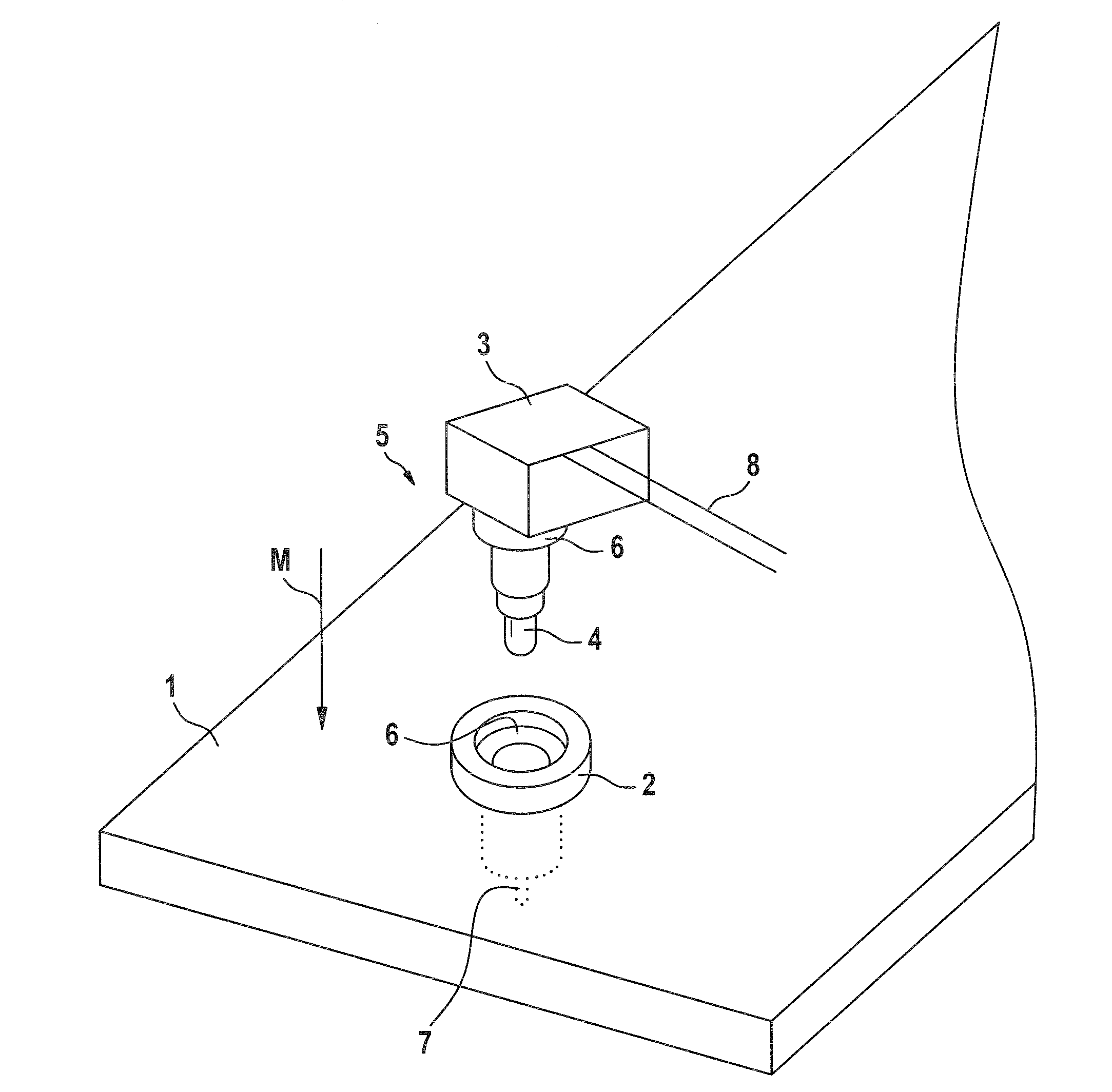
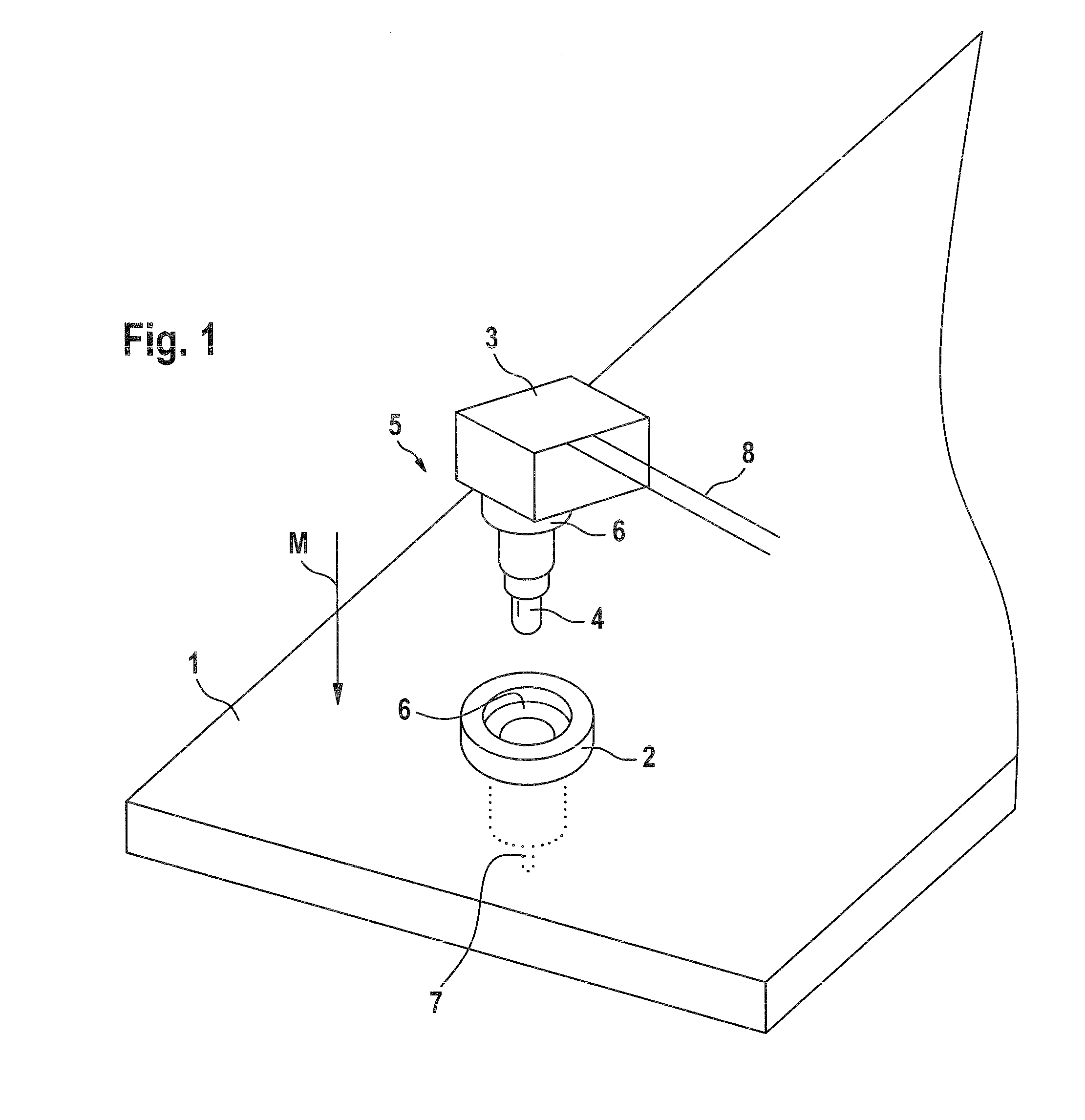
[0036]FIG. 1 shows an exploded illustration of a portion of an interior trim element 1. The interior trim element 1 has a bush 2, into which an LED-based luminous means, in the present case a light-emitting diode (LED) 4 retained and accommodated in a cube-like housing 3, can be inserted. The housing 3 with LED 4 is designated hereinafter as housed LED 5.

[0037]The bush 2 and the housed LED 5 have mutually corresponding holding elements 6, by means of which the housed LED 5 can be retained securely in the bush 2. The holding elements 6, which e.g. enable the housed LED 5 to be retained in a positively locking and / or force-locking manner, can furthermore or alternatively have latching elements, by means of which the housed LED 5 can be latched, more particularly latched in a releasable manner, in the bush 2.

[0038]In the mounted state, the LED 4 integrated with the cube-like housing 3 is situated in the bush 2, which is incorporated at least partly into the interior trim element 1. In ...


PUM


Abstract

The present invention is directed to a luminous means comprising at least one light-emitting diode which is at least partly accommodated in a connection block, wherein electrical connections of the at least one light-emitting diode exit from the connection block in an angled fashion relative to the preferred light emission direction (M). The invention is further directed to a cable harness comprising at least one of said luminous means, as well as to an interior trim element comprising said luminous means.

Description

BACKGROUND OF THE INVENTION[0001]In the case of aircraft cabins it is known to provide ceiling or wall lining elements with luminous means incorporated therein. When the luminous means are driven in a suitable manner, one or more desired luminous patterns can be represented. Such a luminous pattern can be, for example, individual light or luminous spots which are distributed over one or more lining elements and in their totality produce an image, such as e.g. a star image representation of the starry sky. In order to generate the light or luminous spots, light-emitting diodes or optical waveguides can be incorporated in the lining element itself. The light-emitting diodes or optical waveguides are usually inserted in holes in the lining elements.DISCUSSION OF THE PRIOR ART[0002]Given complex distribution of the light or luminous spots over a lining element, the outlay for equipment with light sources and the cabling thereof is extremely high. For equipment and / or cabling purposes, a...

Claims


Application Information

Patent Timeline
IPC IPC(8): F21V21/00F21V11/00
CPCB60Q2500/10B64C2027/8236B64D11/00B64D2011/0038F21S2/005F21V21/04H02G3/32F21W2101/06F21W2101/08F21W2121/008F21Y2101/02H01L33/54F21V27/00F21Y2115/10B60Q3/54F21W2107/30F21W2106/00F21K99/00F21V19/001H01B7/0045H01L33/62
Inventor SCHEVARDO, DIRK-ACHIMANHORN, ULLIKLETTKE, OLIVERSCHLOSSER, RUDIGERGEUDNER, THOMAS
Owner DIEHL AIRCABIN
Why Eureka
Try Eureka