
Battery assembly

a battery and assembly technology, applied in the field of battery assembly, can solve the problems of excessive installation space and significant increase in thickness of battery assembly, and achieve the effect of reducing the number of components to be assembled in assembling the battery assembly, efficient cooling structure and reducing volume efficiency

Active Publication Date: 2012-03-01
GS YUASA INT LTD
View PDF5 Cites 57 Cited by
  • Summary
  • Abstract
  • Description
  • Claims
  • Application Information

AI Technical Summary

Benefits of technology

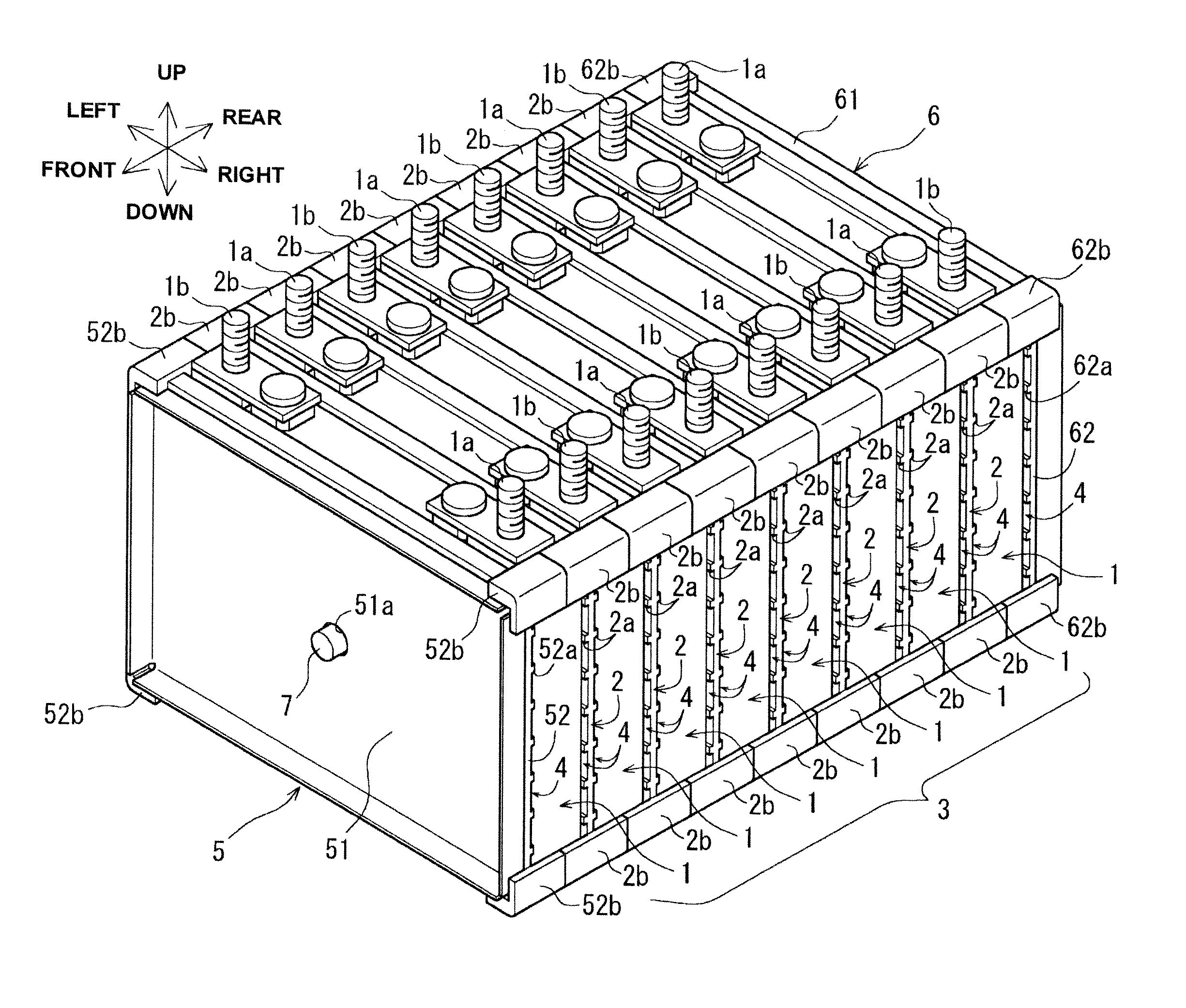
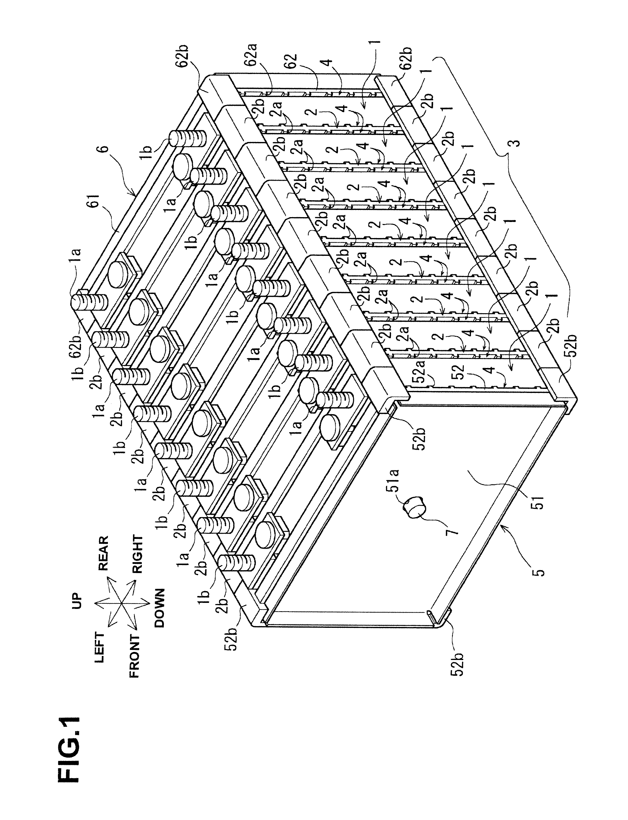
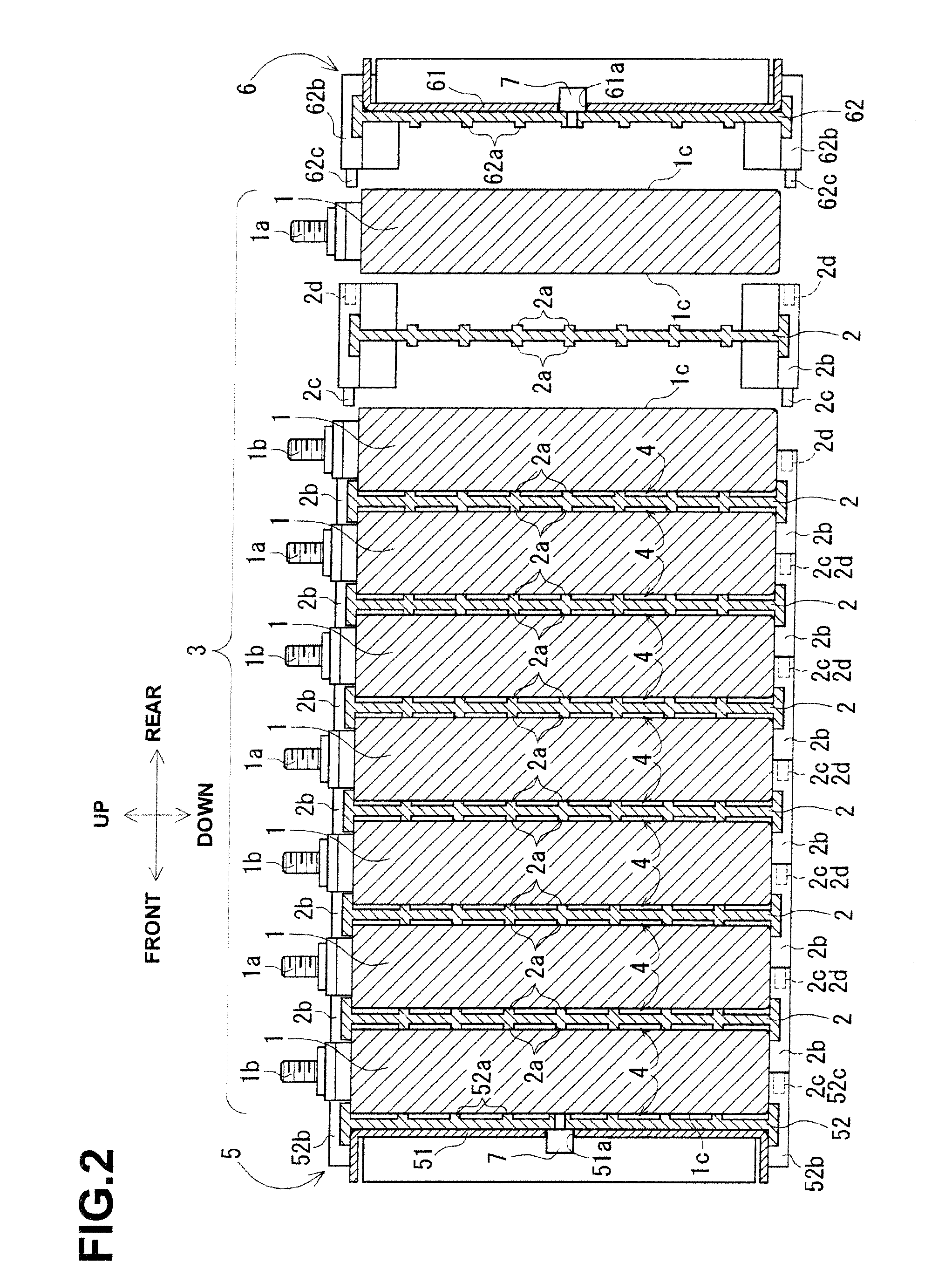
The present invention provides a battery assembly with improved insulation and cooling efficiency, while also reducing the number of components to be assembled and facilitating assembly. The battery assembly includes a plurality of batteries arranged in a given direction, battery holders disposed between the batteries, and a pair of end plates disposed on an outside of the batteries. The end plates are fixed to the batteries using a clamp fixing means, and at least one of the end plates includes a metal plate and an insulating plate integrally fixed to the inner side. This design reduces deflection of the end plates and improves battery assembly efficiency.

Problems solved by technology

For example, in Patent Document 2, since end plates made of resin are used as illustrated in FIGS. 1 to 4, the thicknesses thereof are significantly increased, and the resulting battery assembly will occupy an excessive installation space.

Method used


Image

  • Battery assembly
  • Battery assembly
  • Battery assembly

Examples


Embodiment Construction

[0042]Hereinafter, an embodiment of the present invention will be described with reference to FIGS. 1 to 7.

[0043]As illustrated in FIGS. 1 and 2, in a battery assembly according to the present embodiment, eight batteries 1 each serving as a rectangular non-aqueous electrolyte secondary battery are arranged. As illustrated in FIG. 3, in each battery 1, an electricity-generating element and / or a non-aqueous electrolyte are / is contained in a rectangular box type metal battery case in which its longitudinal width is shorter than its vertical height or lateral length. Further, a positive terminal 1a and a negative terminal 1b are attached to lateral ends of a lid plate constituting an upper surface of the battery case.

[0044]Since surfaces of the battery cases, which face in a longitudinal direction, serve as lateral surfaces 1c each having the largest area, the batteries 1 are arranged longitudinally in such a manner that the lateral surfaces 1c are opposed to each other and battery hold...


PUM

PropertyMeasurementUnit
insulating propertyaaaaaaaaaa
areaaaaaaaaaaa
strengthaaaaaaaaaa

Abstract

There is provided a battery assembly wherein assembly can be facilitated by reducing the number of components to be assembled, by integrally fixing resin plates (52, 62) on the inside of metal plates (51, 61) of end plates (5, 6). A laminated battery body (3) is constituted by adjacently arranging battery holders (2) made of resin forming cooling passages (4) between a plurality of batteries (1) and holding such batteries (1) on both sides between other batteries (1). The metal plates (51, 61) and resin plates (52, 62) that are integrally fixed on the inside of these metal plates are provided on the outside of the batteries (1) at both ends of the laminated battery body (3). Thus, the batteries (1) are held by the resin plates (52, 62), and the end plates (5, 6) are respectively arranged to form the cooling passages (4) between these batteries (1) and the metal plates (51, 61). The laminated battery body (3) is fixed in a clamped manner by fixing means clamping these end plates (5, 6).

Description

TECHNICAL FIELD[0001]The present invention relates to a battery assembly in which a plurality of batteries, arranged via battery holders, are fixed in a clamped manner from both sides by end plates.BACKGROUND ART[0002]In an electric vehicle or the like, a large-capacity storage battery is required, and therefore, a battery assembly in which a large number of batteries are arranged and fixed is used. Further, as such a battery assembly, there has been proposed a battery assembly in which a plurality of batteries, arranged via battery holders made of resin, are fixed in a clamped manner from both sides by end plates made of resin or metal (see Patent Document 1 and Patent Document 2, for example).[0003]The respective batteries of the foregoing battery assembly are arranged in such a manner that lateral surfaces of rectangular box type metal battery cases, each having the largest area, are opposed to each other, and battery holders made of resin are each placed between the adjacent bat...

Claims


Application Information

Patent Timeline
Patent Type & Authority Applications(United States)
IPC IPC(8): H01M2/10H01M10/50H01M50/103H01M50/209H01M50/224H01M50/264
CPCH01M2/1077H01M10/0481H01M10/486H01M10/5016H01M10/5067H01M10/5065H01M10/5004H01M10/5059H01M10/5032H01M50/209H01M50/224H01M50/264H01M50/103H01M10/625H01M10/6563H01M10/647H01M10/6557H01M10/613H01M10/6562Y02E60/10Y02P70/50H01M10/658H01M10/4285H01M2220/20H01M50/593H01M10/6556H01M10/48H01M50/20H01M50/119Y02T10/70
Inventor YOSHITAKE, SHINSUKEOKAMOTO, KATSUHIKONAKAMURA, JUNSASAKI, TAKESHI
Owner GS YUASA INT LTD
Learn More