Controller for and method of controlling internal combustion engine

a technology of internal combustion engine and controller, which is applied in the direction of electric control, machines/engines, instruments, etc., can solve the problems of complex sensor construction, thermal strain in constituent parts, and sensor output error, and achieve the effect of simple calculation

Inactive Publication Date: 2012-03-01
TOYOTA JIDOSHA KK
View PDF6 Cites 4 Cited by
  • Summary
  • Abstract
  • Description
  • Claims
  • Application Information

AI Technical Summary

Benefits of technology

[0007]The invention provides a controller for an internal combustion engine equipped with a cylinder pressure sensor, the controller being capable of correcting the errors in the output caused by thermal strain of the cylinder pressure sensor by simple calculation.

Problems solved by technology

Thus, when the sensor is exposed to a high-temperature gas, there is a fear that a thermal strain occurs in constituent parts and an error is caused in the output from the sensor.
However, when it is tried to improve the pressure measurement accuracy in terms of the hardware of the sensor as in the case of the above-described conventional cylinder pressure sensor, the construction of the sensor becomes complicated, which reduces practicality.

Method used


Image

  • Controller for and method of controlling internal combustion engine
  • Controller for and method of controlling internal combustion engine
  • Controller for and method of controlling internal combustion engine

Examples


first embodiment

Specific Process of First Embodiment

[0102]Next, referring to FIG. 7, a specific process of the first embodiment will be described. FIG. 7 is a flow chart showing a routine, by which the ECU 40 corrects the thermal strain error.

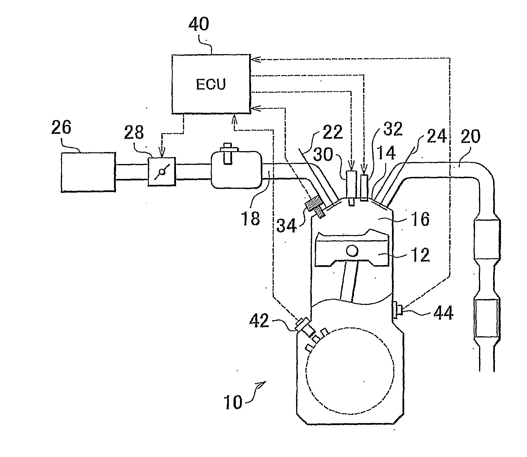
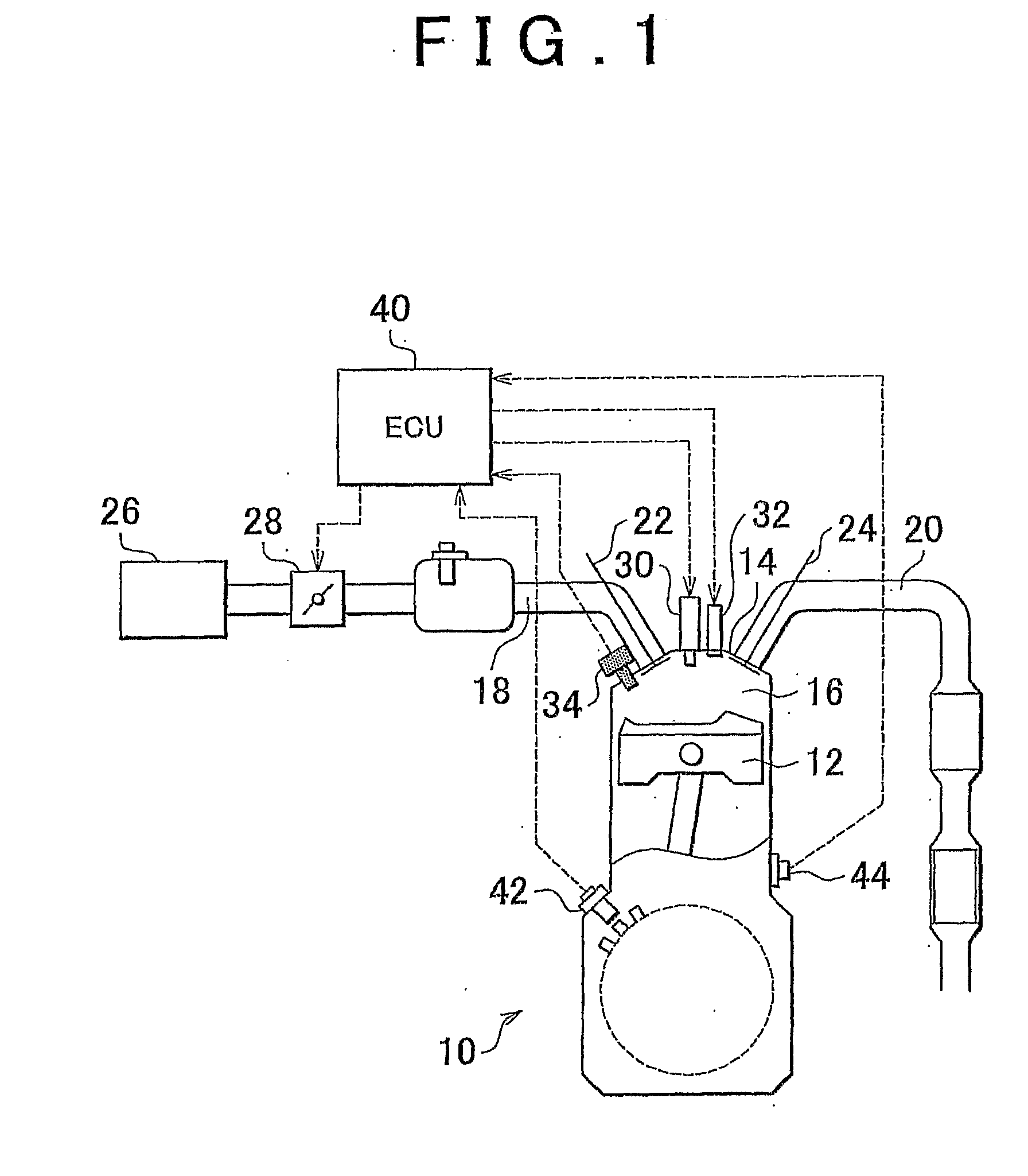
[0103]In the routine shown in FIG. 7, first, a cylinder pressure is acquired (step 100). Specifically, in this step, the cylinder pressure P(θ) at a crank angle θ is detected with the use of the cylinder pressure sensor 34. Subsequently, the value of PVκ(θ) is calculated (step 102). Specifically, in this step, the value of PVκ(θ) at the crank angle (θ) is calculated based on the cylinder pressure P(θ) acquired in step 100, the cylinder volume V(θ) at the time of detecting the cylinder pressure, and the specific heat ratio κ of the gas in the cylinder.

[0104]Next, the crank angle θfix, at which the value of PVκ(θ) peaks, is detected (step 104). Specifically, in this step, the crank angle θfix, at which the value of PVκ(θ) calculated in the above step 102 peaks, ...

second embodiment

Specific Process of Second Embodiment

[0124]Next, referring to FIG. 10, a specific process of the second embodiment will be described. FIG. 10 is a flow chart showing a routine, by which the ECU 40 corrects the thermal strain error.

[0125]In the routine shown in FIG. 10, it is determined whether the engine speed is lower than a predetermined value α (step 200). As the predetermined value α, a predetermined value is read in as the maximum engine speed, up to which the cooling loss of the internal combustion engine 10 can affect the calculation of PVκ. As a result, when it is determined that the relation, (engine speed)κ. Then, the process proceeds to the next step and the water temperature of the internal combustion engine 10 is detected (step 202).

[0126]Next, the cooling loss coefficient Kcool is read in from a map (step 204). FIG. 11 is a map for determining the cooling loss coefficient Kcool. In this step, the coefficient Kcool corresponding to the engine speed and the water tempera...

third embodiment

Specific Process of Third Embodiment

[0139]Next, referring to FIG. 13, a specific process of this embodiment will be described. FIG. 13 is a flow chart showing a routine, by which the ECU 40 corrects the thermal strain error.

[0140]In the routine shown in FIG. 13, first, a cylinder pressure P(θ) is acquired (step 300). Subsequently, the value of PVκ(θ) is calculated (step 302). Next, the crank angle θfix, at which the value of PVκ(θ) peaks, is detected (step 304). Specifically, in these steps, the processes similar to those of the above steps 100 to 104 are performed.

[0141]Next, a cooling loss coefficient Kw is read in from a map (step 306). Specifically, in this step, first, the engine speed and the water temperature of the internal combustion engine 10 are detected. Next, Kw is determined that corresponds to the detected engine speed and water temperature with the use of a multidimensional map in which the engine speed and the water temperature are parameters. With this map, the low...


PUM


Abstract

Heat generation amount PVκ(θ) is calculated with the use of cylinder pressure P(θ), detected by a cylinder pressure sensor, cylinder, volume V(θ), and specific heat ratio κ (steps 100 to 102). A crank angle θfix, at which the value of PVκ(θ) peaks, is determined as a start crank angle, at which an adiabatic process after combustion starts (step 104). A correction coefficient Kfix is calculated based on the variation of the value of PVκ(θ) after θfix (step 106). An actual heat generation amount PVκ(θ) is calculated with the use of the correction coefficient Kfix (step 110). A cooling loss coefficient Kcool that determines a correlation between the cooling loss and crank angles may be calculated based on a water temperature and an engine speed and the actual heat generation amount PVκfix(θ) may be made to reflect the cooling loss coefficient Kcool.

Description

BACKGROUND OF THE INVENTION[0001]1. Field of the Invention[0002]The invention relates to an internal combustion engine controller and a method of controlling an internal combustion engine, and in particular to a controller for and a method of controlling an internal combustion engine equipped with a cylinder pressure sensor.[0003]2. Description of the Related Art[0004]The sensitivity of a cylinder pressure sensor varies with time and there are individual differences in sensitivity between the cylinder pressure sensors. Thus, Japanese Patent Application Publication No. 2005-351146 (JP-A-2005-351146), for example, discloses an internal combustion engine controller that makes it possible to estimate the sensitivity of the cylinder pressure sensor. More specifically, in this controller, an estimate of the sensitivity of the cylinder pressure sensor is calculated based on the cylinder pressure at a predetermined crank angle θ0 in an intake stroke, the intake air pressure at the point, at...

Claims


Application Information

Patent Timeline
Patent Type & Authority Applications(United States)
IPC IPC(8): F02D28/00
CPCF02D35/02F02D35/023F02D35/024F02D2041/281F02D41/222Y02T10/40F02D35/028
Inventor YASUDA, HIROMICHISUZUKI, YUSUKE
Owner TOYOTA JIDOSHA KK
Why Eureka
Try Eureka