
Shaving Head with Multiple Shaving Units

a shaving head and shaving head technology, applied in the field of shaving heads, can solve the problems of skin irritation and the performance of the known cutting system not being optimal, and achieve the effects of high flexibility, high closeness, and optimal shaving quality

Active Publication Date: 2012-03-08
BRAUN GMBH
View PDF21 Cites 17 Cited by
  • Summary
  • Abstract
  • Description
  • Claims
  • Application Information

AI Technical Summary

Benefits of technology

The present invention provides an improved shaving head for electric shavers that can shave hairs on both flexible and less flexible skin regions with high closeness and without skin irritations. The shaving head comprises two different kinds of trimmer-type cutting units, a first trimmer-type cutting unit with slots and teeth, and a second trimmer-type cutting unit with slits. These units work together as a system of coordinated components and fine tuned cutting units, delivering a shaving performance with an additional synergistic effect. The shaving head also includes a foil-type cutting unit between the two trimmer-type cutting units, which ensures optimal contact and adaptation to the skin contour and avoids skin irritations. The cutting units are interconnected with vertical play via coupling elements, which limits exposure of single cutting units and prevents skin deformations and irritations. The outer cutter of the foil-type cutting unit is shaped semi-cylindrically along its longitudinal axis, and the first trimmer-type cutting unit has a concave top surface and the second trimmer-type cutting unit has a convex or roof-shaped surface, which enhances the lifting of flat laying hairs during shaving. The second trimmer-type cutting unit also has two comb elements disposed opposite each other, which further improves the feeding performance.

Problems solved by technology

With respect to hairs which are resting flat against the skin the performance of the known cutting system is not optimal since such hairs—especially if they are located on skin areas with flexible skin—tend to escape from the feeding area formed between two teeth of the comb-shaped feeding means.
The drawback of this kind of shaving units is the risk to cause skin irritations.

Method used


Image

  • Shaving Head with Multiple Shaving Units
  • Shaving Head with Multiple Shaving Units
  • Shaving Head with Multiple Shaving Units

Examples


Embodiment Construction

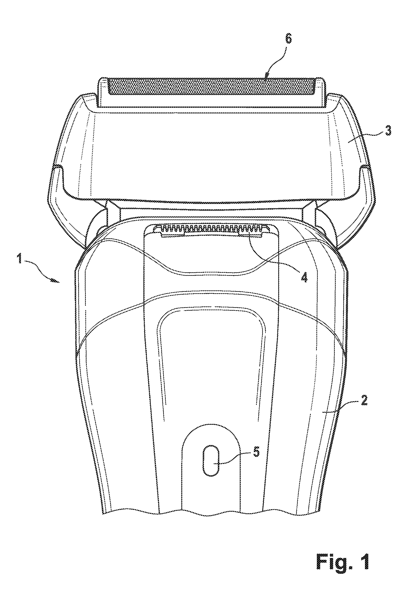
[0018]FIG. 1 shows an illustration of an electric shaver in general. It essentially consists of a housing 2 carrying at its top a shaving head 3 and at the front part of the housing 2 a long-hair clipper 4. Inside the housing 2 there is arranged an electric motor for driving all the cutting parts when the shaver is switched on via the ON / OFF switch 5. The electric motor is not shown in the drawing.

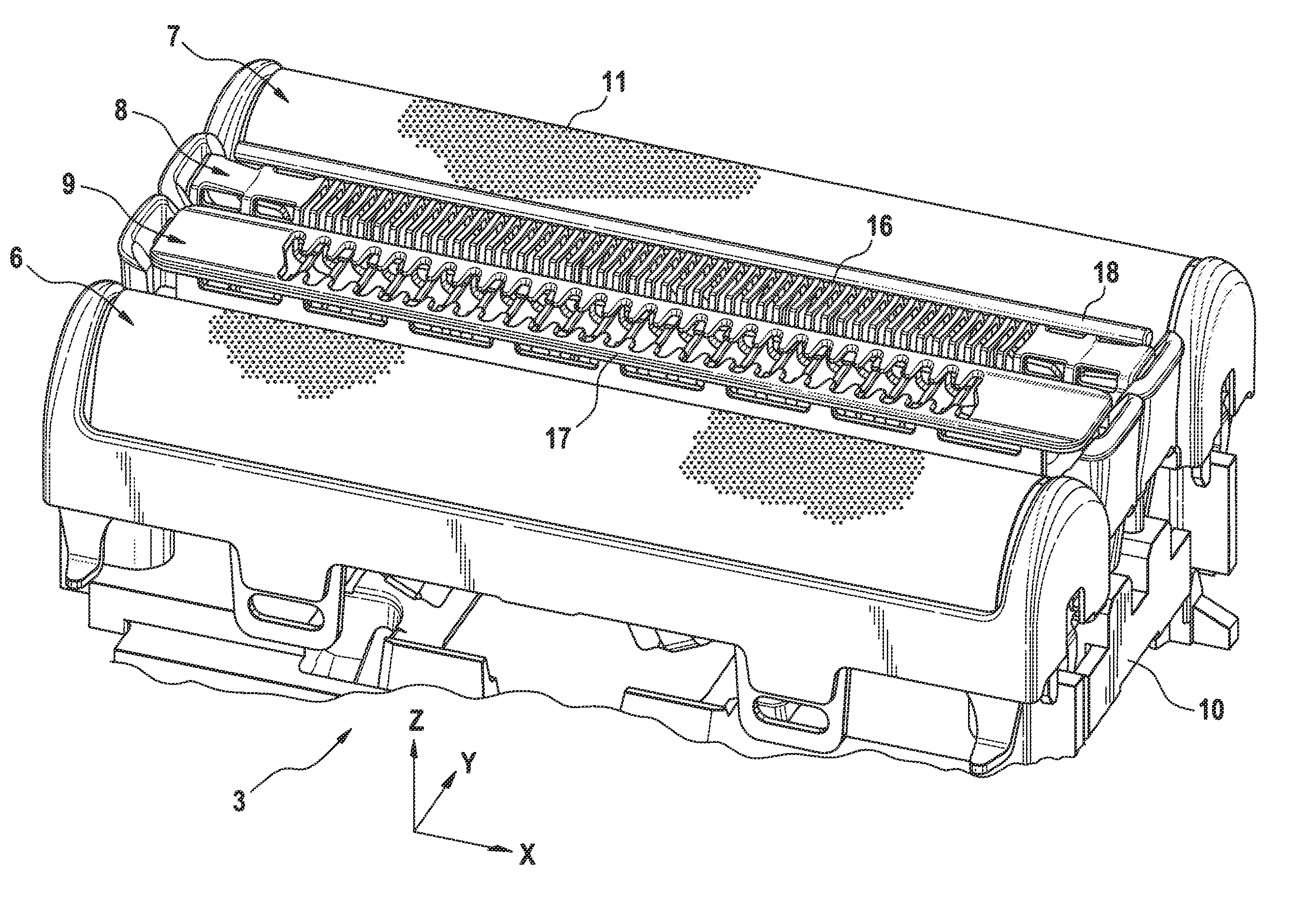
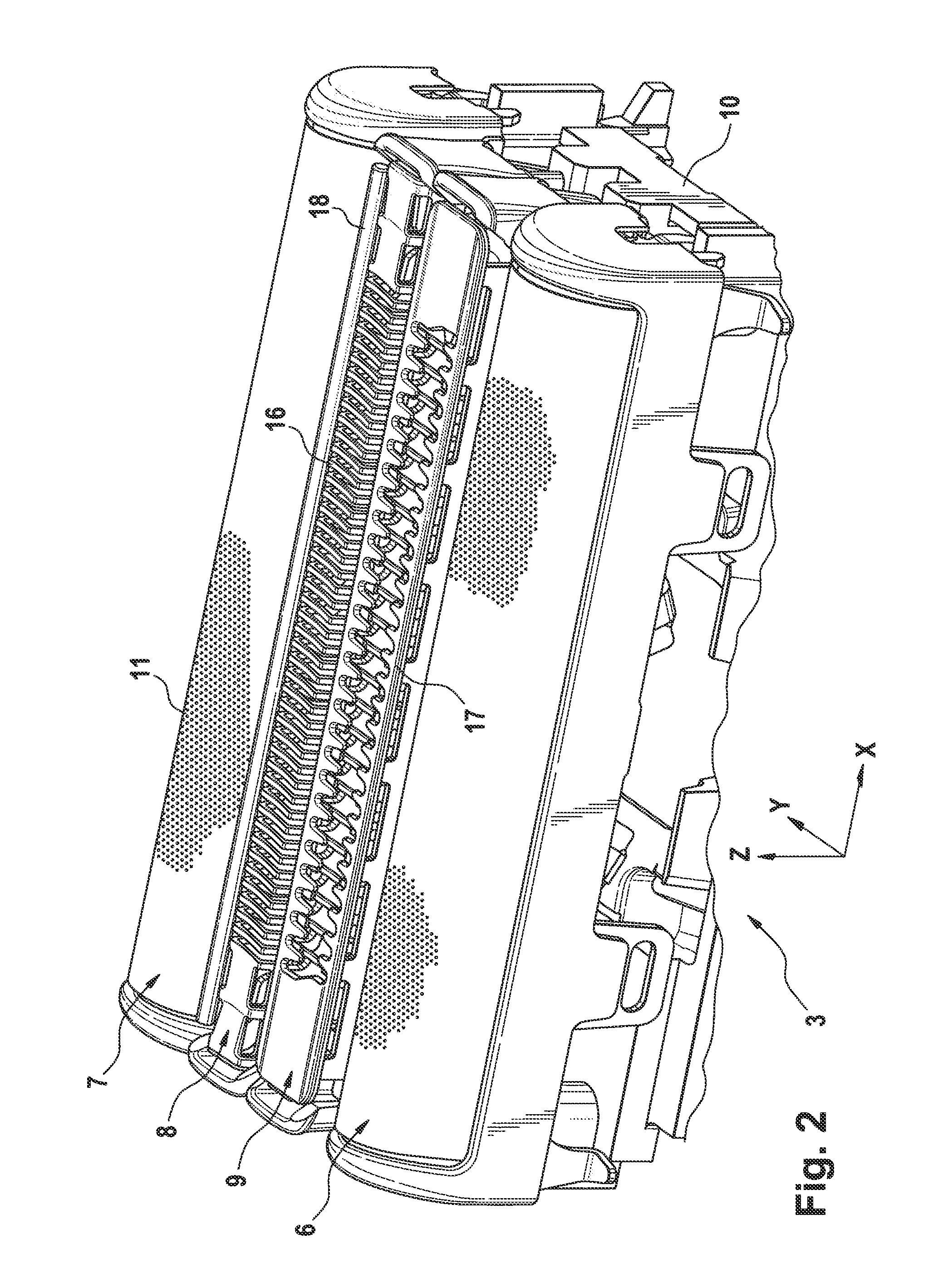
[0019]FIG. 2 gives an enlarged perspective top view of the shaver head 3 depicting all the four cutting units which are the first foil-type cutting unit 6, the second foil-type cutting unit 7, the first trimmer-type cutting unit 8 and the second trimmer-type cutting unit 9. According to this embodiment the two foil-type cutting units 6, 7 are identical while the two trimmer-type cutting units 8, 9 differ from each other in their design. However, also the foil-type cutting units might be of different size, shape or may have different perforations. All the four cutting units are floatably mo...


PUM


Abstract

A shaving head for an electric dry shaver which comprises a base element for carrying at least three cutter units, each providing an outer cutter and an inner cutter arranged to be moved in sliding contact relative to each other, whereby at least one cutter unit comprises a foil-type outer cutter. The shaving head further comprises a first trimmer-type cutting unit that has a plurality of slots defined by a plurality of adjacent bar elements featuring cutting edges. The shaving head comprises a second trimmer-type cutting unit having an outer cutter that comprises a plurality of teeth featuring cutting edges and spaced from each other so as to define a plurality of slits.

Description

FIELD OF THE INVENTION[0001]This invention relates to a shaving head for an electric dry shaver according to the generic part of claim 1. It is especially directed to dry shavers having a shaving head with multiple cutting units.BACKGROUND OF THE INVENTION[0002]Shaving heads of the type initially referred to are known for example from EP 0693988 B1. This document discloses an electric dry shaver where a center trimmer is arranged between two foil type shaving elements. The upper cutter of this center trimmer is provided with hair feeding means consisting of projecting teeth which are directed outwardly. Those center trimmers in general are rather effective in cutting the hairs to a very short remaining length of hair. With respect to hairs which are resting flat against the skin the performance of the known cutting system is not optimal since such hairs—especially if they are located on skin areas with flexible skin—tend to escape from the feeding area formed between two teeth of th...

Claims


Application Information

Patent Timeline
Patent Type & Authority Applications(United States)
IPC IPC(8): B26B19/26
CPCB26B19/04B26B19/10B26B19/06
Inventor POHL, THORSTENKRAUSS, JOACHIMSCHWARZ, TOBIASJUNK, PETEREICHHORN, REINHOLDPETER, ANDREASODEMER, MICHAELFUELLGRABE, MARTINZEGULA, CHRISTOPHKOEPPL, ALOISFUERST, STEFAN
Owner BRAUN GMBH
Learn More