Vehicle component mounting arrangement

a technology for mounting arrangements and vehicles, which is applied to vehicle sub-unit features, cell components, batteries, etc., can solve problems such as difficulty in balancing the weight of vehicles, and achieve the effect of facilitating the balance of vehicles' weigh

Active Publication Date: 2012-03-08
NISSAN MOTOR CO LTD
View PDF3 Cites 35 Cited by
  • Summary
  • Abstract
  • Description
  • Claims
  • Application Information

AI Technical Summary

Benefits of technology

[0007]One object of the present invention is to provide an electrical component mounting structure for an electric vehicle that enables the weight of the vehicle to be balanced more easily.

Problems solved by technology

It has been discovered that when a large number of comparatively heavy electrical components (e.g., an electric motor, an inverter, and a charger) are concentrated in one portion of a vehicle, it is difficult balance the weight of the vehicle.

Method used


Image

  • Vehicle component mounting arrangement
  • Vehicle component mounting arrangement
  • Vehicle component mounting arrangement

Examples


Embodiment Construction

[0015]Selected embodiments will now be explained with reference to the drawings. It will be apparent to those skilled in the art from this disclosure that the following descriptions of the embodiments are provided for illustration only and not for the purpose of limiting the invention as defined by the appended claims and their equivalents.

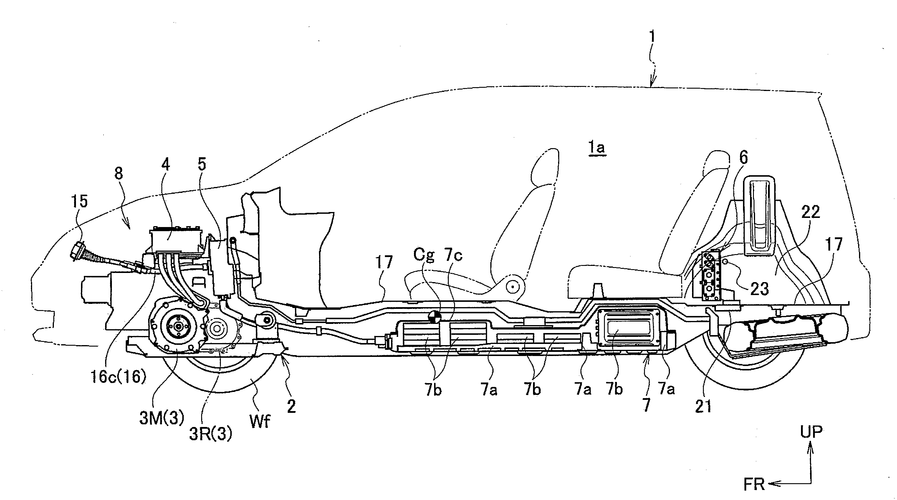
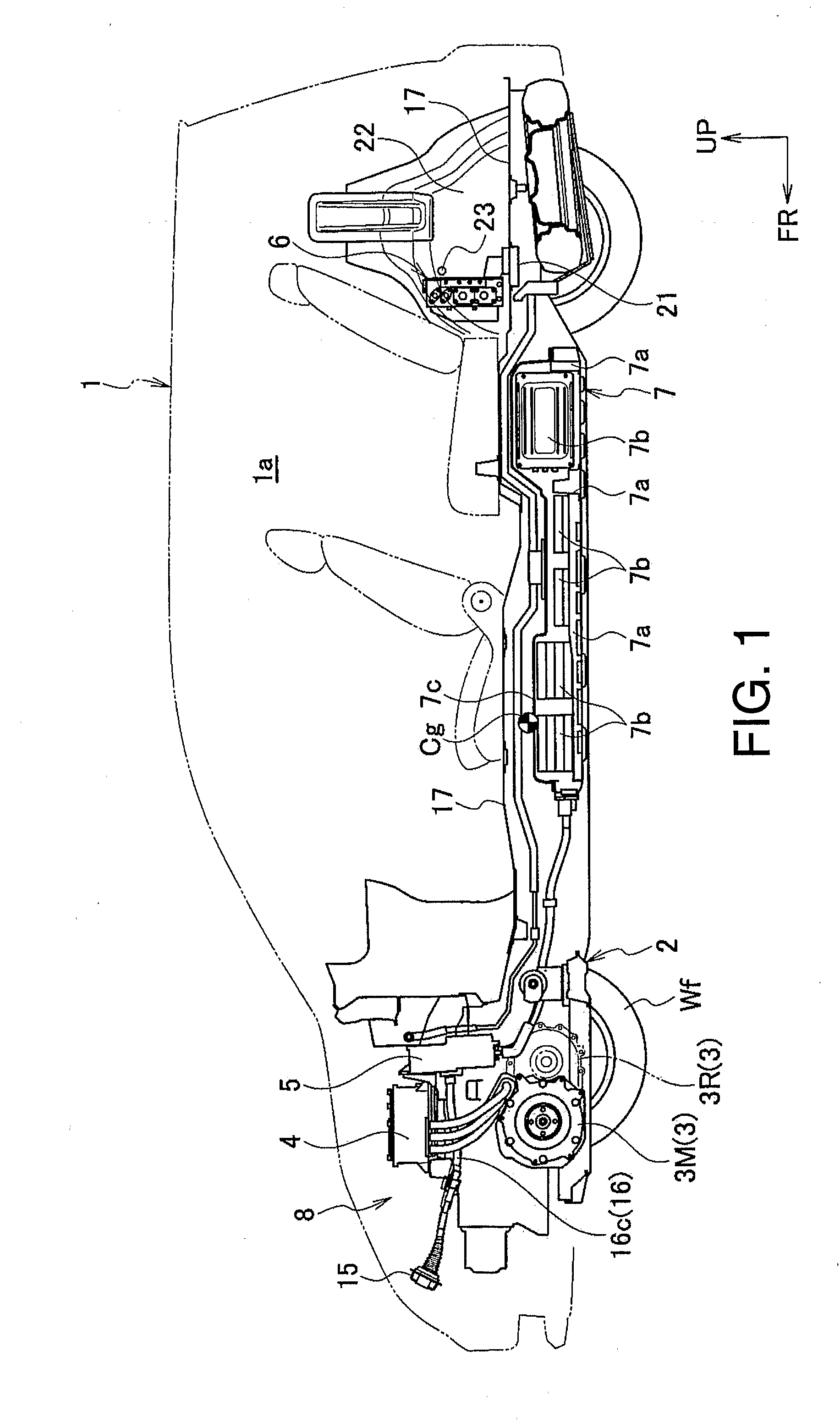
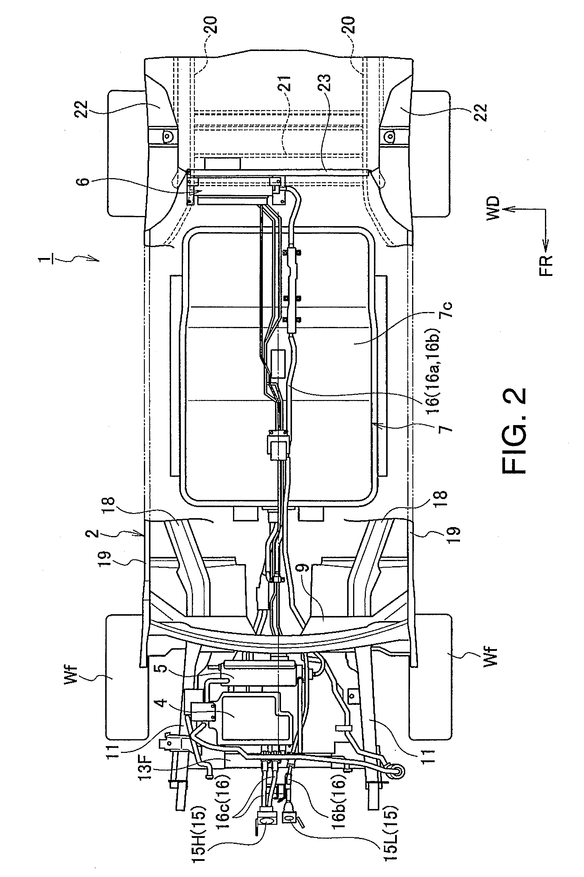
[0016]Referring initially to FIGS. 1 and 2, a portion of an electric vehicle 1 is partially illustrated with an electric vehicle component mounting arrangement in accordance with a first embodiment. In the figures, an arrow FR indicates a frontward direction of the vehicle, an arrow UP indicates an upward direction of the vehicle, and an arrow WD indicates a widthwise direction of the vehicle.

[0017]In this embodiment, the vehicle 1 includes a vehicle body 2 that supports a power unit 3 that includes an electric motor 3M and a reduction gear 3R. The electric motor 3M and the reduction gear 3R are configured as a single integrated unit. The electric...


PUM


Abstract

A vehicle component mounting structure is provided with a vehicle body, a battery, a charger, a high-power electrical component other than the charger. The battery is mounted on the vehicle body. The charger is mounted on the vehicle body and converts a lower-voltage electric power supplied thereto from an external source into a higher-voltage electric power that is supplied to the battery. The high-power electrical component is mounted on the vehicle body with high voltage being supplied to the high-power electrical component. The charger and the high-power electrical component are arranged on longitudinally opposite sides of the battery with respect to a longitudinal direction of the vehicle body.

Description

CROSS-REFERENCE TO RELATED APPLICATIONS[0001]This application claims priority to Japanese Patent Application Nos. 2009-124249 filed May 22, 2009, 2009-166937 filed Jul. 15, 2009 and 2010-005092 filed Jan. 13, 2010. The entire disclosures of Japanese Patent Application Nos. 2009-124249, 2009-166937 and 2010-005092 are hereby incorporated herein by reference.BACKGROUND[0002]1. Field of the Invention[0003]The present invention generally relates to a component mounting structure for an electric vehicle. More specifically, the present invention relates to a vehicle component mounting arrangement in which electrical components are arranged within an electric vehicle.[0004]2. Background Information[0005]Electric vehicles often include an electric motor, an inverter, a charger and other electrical components. These electrical components are sometimes arranged in a concentrated fashion in a frontward portion of the vehicle. One example of such an electric vehicle is disclosed in Japanese Lai...

Claims


Application Information

Patent Timeline
Patent Type & Authority Applications(United States)
IPC IPC(8): B60K1/04B60L11/18
CPCB60K1/04B60K2001/001B60K2001/0438B60L11/1879B60L11/18B60Y2400/61Y02T10/7005Y02T10/705B60Y2400/214B60K1/00B60L1/003B60L1/04Y02T10/7072Y02T90/14B60L53/16B60L50/51B60L53/11B60L50/66B60L50/64Y02T10/70Y02E60/10B60L53/14B60Y2200/91H01M2220/20Y02T90/12H01M50/20
Inventor IWASA, MAKOTOMORI, NOBUHIROSHIGEMATSU, SATOSHITAMURA, KENJI
Owner NISSAN MOTOR CO LTD
Why Eureka
Try Eureka