Suspension device

a suspension device and suspension technology, applied in the direction of springs/dampers, shock absorbers, mechanical devices, etc., can solve the problems of suspension device becoming larger in its outside diameter, suspension device becoming too large upon maximum extension of both actuators and hydraulic dampers, etc., to achieve the effect of reducing the outside diameter of the suspension device and reducing the weight of the suspension devi

Active Publication Date: 2009-12-31
KYB CORP
View PDF9 Cites 36 Cited by
  • Summary
  • Abstract
  • Description
  • Claims
  • Application Information

AI Technical Summary

Benefits of technology

[0009]According to the suspension device of the present invention, since a stopper is provided on the outer periphery of the air piston and a stopper seat for abutment against the stopper upon maximum extension of the suspension device is provided on the inner periphery of the air chamber, such a tubular member having a member for abutment against a stopper as in the prior art is not required to be installed on the motor side, and hence, the weight of the suspension device can be so much reduced. Moreover, since it is not necessary to install tubes for restricting a maximum extension length, it is not required to ensure clearances that are needed in case of installing the tubes. Consequently, it is possible to reduce the outside diameter of the suspension device.

Problems solved by technology

Thus, the whole of the suspension device may become too long upon maximum extension of both actuator and hydraulic damper.
Since the aforesaid tubular member is installed for the purpose of restricting the maximum extension length of the suspension device and disposing a sealing member on the outer periphery of the hydraulic damper, it is designed to be long, having a diameter permitting its insertion between an air piston and the hydraulic damper, and hence heavy.
Consequently, there is a fear of the suspension device becoming larger in its outside diameter.

Method used


Image

  • Suspension device
  • Suspension device

Examples


Embodiment Construction

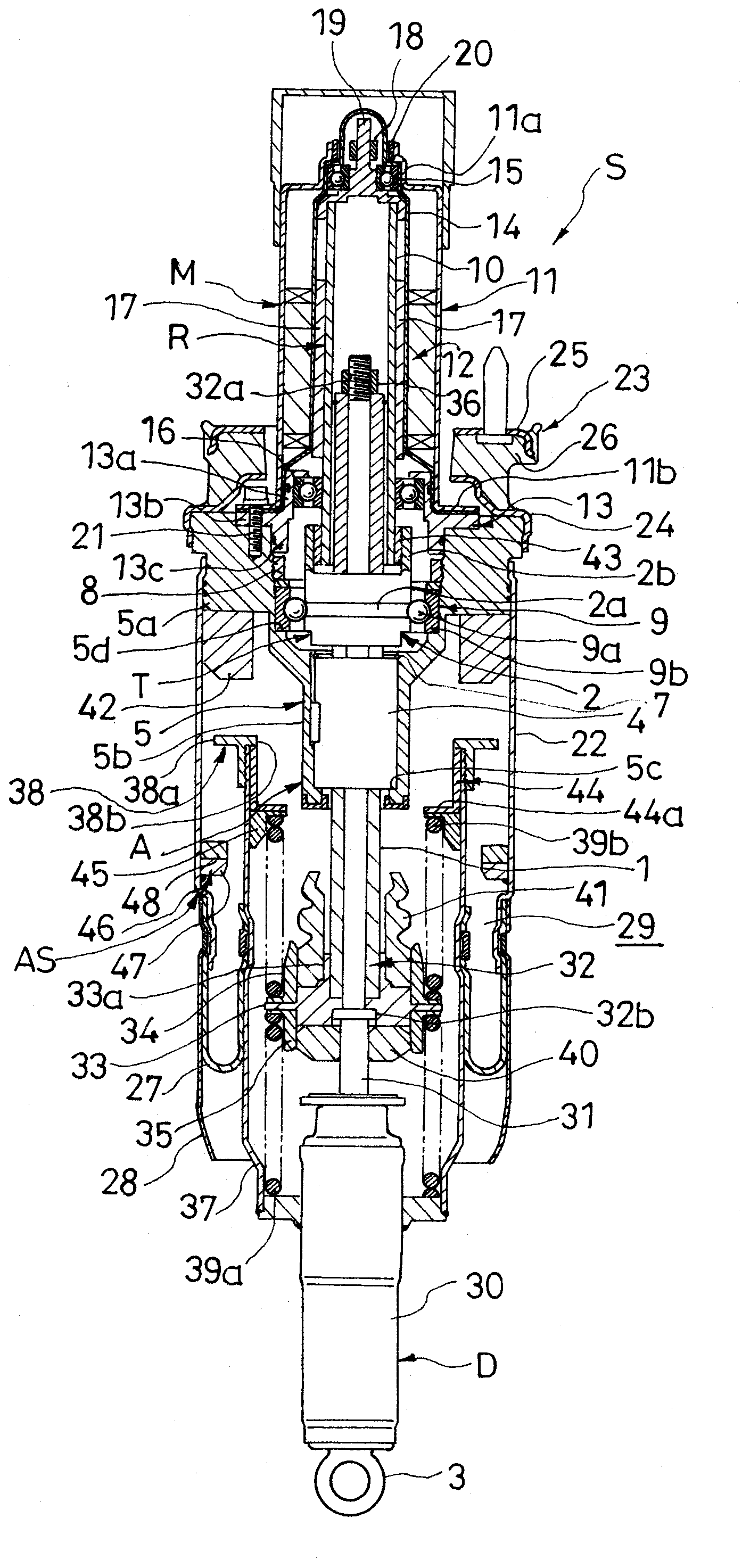
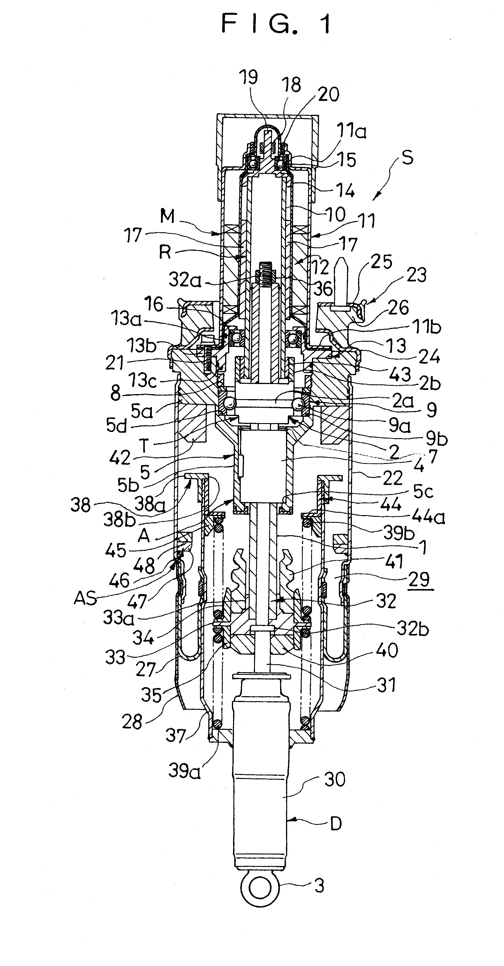
[0011]The present invention will now be described on the basis of an embodiment thereof illustrated in the drawing. As shown in FIG. 1, a suspension device S according to an embodiment of the present invention basically comprises an actuator A, the actuator A including a motion transforming mechanism T for transforming a linear motion of a screw shaft 1 as a linear motion member into a rotational motion of a ball screw nut 2 as a rotating member and a motor M connected to the ball screw nut 2 in the motion transforming mechanism T; an air spring AS, the air spring AS including a tubular air chamber 22 connected to the motor M, an air piston 37 connected to the linear motion member 1 and being tubular and smaller in diameter than the air chamber 22, and a diaphragm27 interposed between the air chamber 22 and the air piston 37; a stopper 38a provided on an outer periphery of the air piston 37; and a stopper seat 46 provided on an inner periphery of the air chamber 22 and adapted to co...


PUM


Abstract

According to problem solving means of the present invention, in a suspension device (S) comprising a motion transforming mechanism (T) for transforming a linear motion of a linear motion member (1) into a rotational motion of a rotating member (2) and a motor (M) connected to the rotating member (2) in the motion transforming mechanism (T), an air spring (AS) is provided, the air spring (AS) including a tubular air chamber (22) connected to the motor (M), an air piston (37) connected to the linear motion member (1) and being tubular and smaller in diameter than the air chamber (22), and a diaphragm (27) interposed between the air chamber (22) and the air piston (37), a stopper (38a) is provided on an outer periphery of the air piston (37), and a stopper seat (46) is provided on an inner periphery of the air chamber (22) so as to be put in abutment against the stopper (38a) upon maximum extension of the suspension device involving relative separation of the air chamber (22) and the air piston (37) with respect to each other.

Description

FIELD OF ART[0001]The present invention relates to an improvement of a suspension device for suppressing a relative movement between a vehicle body and an axle with use of an electromagnetic force developed in a motor.BACKGROUND ART[0002]As a suspension device of this type, there is known such a suspension device as is disclosed in Japanese Patent Laid-Open Publication No. 2007-292255. This conventional suspension device is composed of an actuator, the actuator having a screw shaft threadably engaged with a ball screw nut rotatably and a motor connected to one end of the screw shaft and fixed to a vehicle body, and a hydraulic damper interposed between an axle and the ball screw nut in the actuator to suppress the transfer of a high-frequency vibration to the vehicle body. A relative movement between the vehicle body and the axle is controlled actively with thrust of the actuator.DISCLOSURE OF THE INVENTION[0003]In the case of the suspension device disclosed in Japanese Patent Laid-...

Claims


Application Information

Patent Timeline
Patent Type & Authority Applications(United States)
IPC IPC(8): F16D57/00
CPCF16F9/052F16F2232/06F16F15/03
Inventor SAKUTA, ATSUSHIKONDO, TAKUHIROTACHI, TAKAYUKI
Owner KYB CORP
Why Eureka
Try Eureka