
Capacitor vehicle having high speed charging ability and method of operating a capacitor vehicle

a capacitor vehicle and high-speed charging technology, applied in the direction of charging stations, battery/fuel cell control arrangements, transportation and packaging, etc., can solve the problems of slow battery charging time and electric vehicles may suffer from range problems that are not easily solved

Inactive Publication Date: 2012-03-08
NEVIN DONALD M
View PDF16 Cites 50 Cited by
  • Summary
  • Abstract
  • Description
  • Claims
  • Application Information

AI Technical Summary

Benefits of technology

[0014]A further embodiment of the invention may allow for the user to select one or both of the onboard capacitor and the onboard battery to be charged at a stationary charging station, which may be of use when charging overnight. In this manner, the user can start the day with a full charge on both the battery and the capacitor. The electric motor could operate directly from charge on the capacitor until exhausted, or could run in a typical manner off the battery, with the capacitor being immediately available or in a short period thereafter to maintain a full charge of the battery until the capacitor is exhausted.
[0016]In this manner it is possible to reduce the required charging times for battery powered electric vehicles. The present invention may be used for any vehicles, including automotive, military, uav (unmanned, autonomous vehicles), and / or boats. Charging stations may use the electric grid, and / or alternatively or additionally solar and wind generation systems.

Problems solved by technology

One disadvantage of battery powered electric vehicles is the slow charging time of the batteries.
Electric vehicles may suffer from range problems that are not solved easily by recharging due to the slow recharging rate of batteries.

Method used


Image

  • Capacitor vehicle having high speed charging ability and method of operating a capacitor vehicle
  • Capacitor vehicle having high speed charging ability and method of operating a capacitor vehicle
  • Capacitor vehicle having high speed charging ability and method of operating a capacitor vehicle

Examples


Embodiment Construction

[0030]In the following description, electric vehicles refer to pure electric vehicles, hybrid vehicles, and / or any vehicle using a battery for some or all of the propulsion of the vehicle.

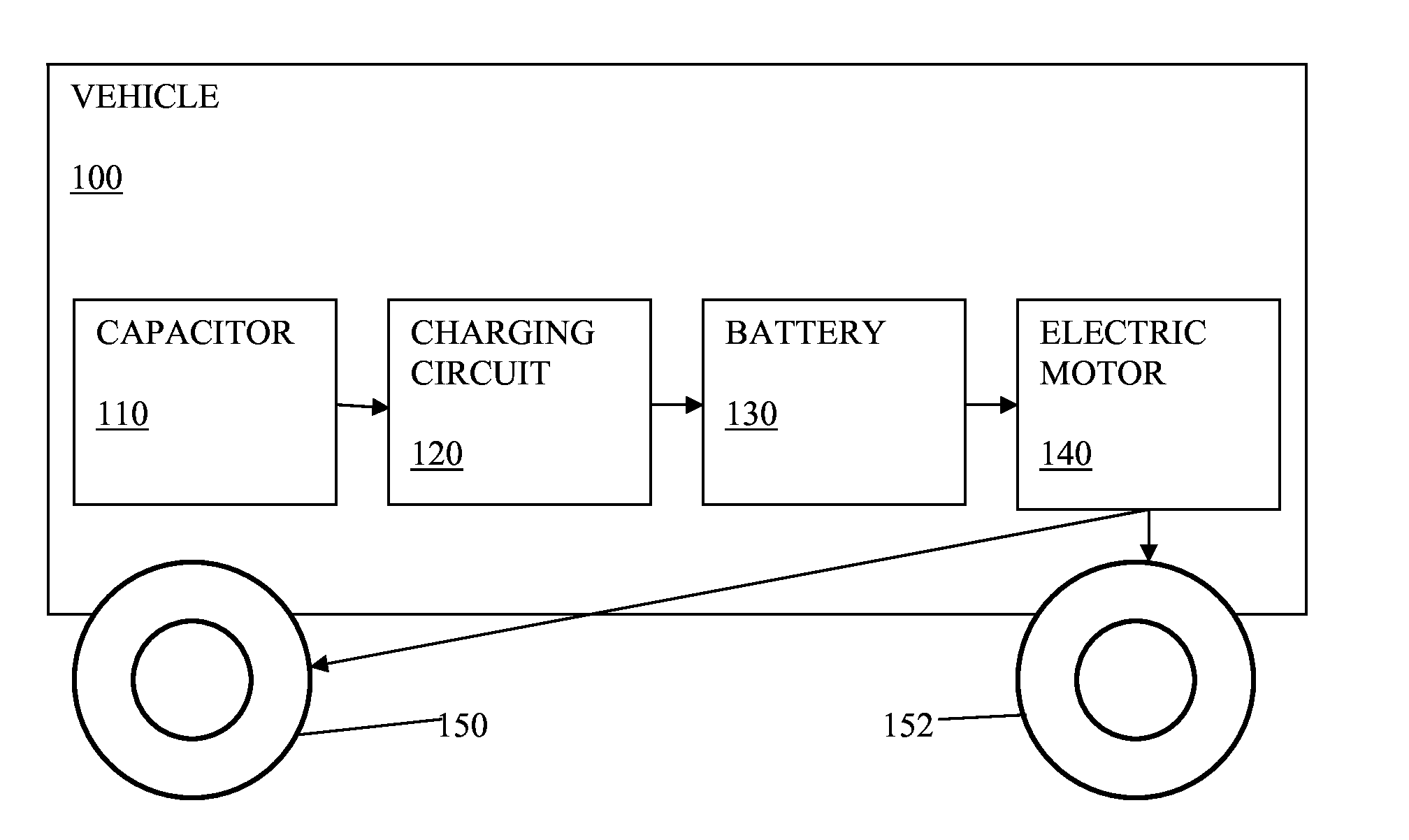
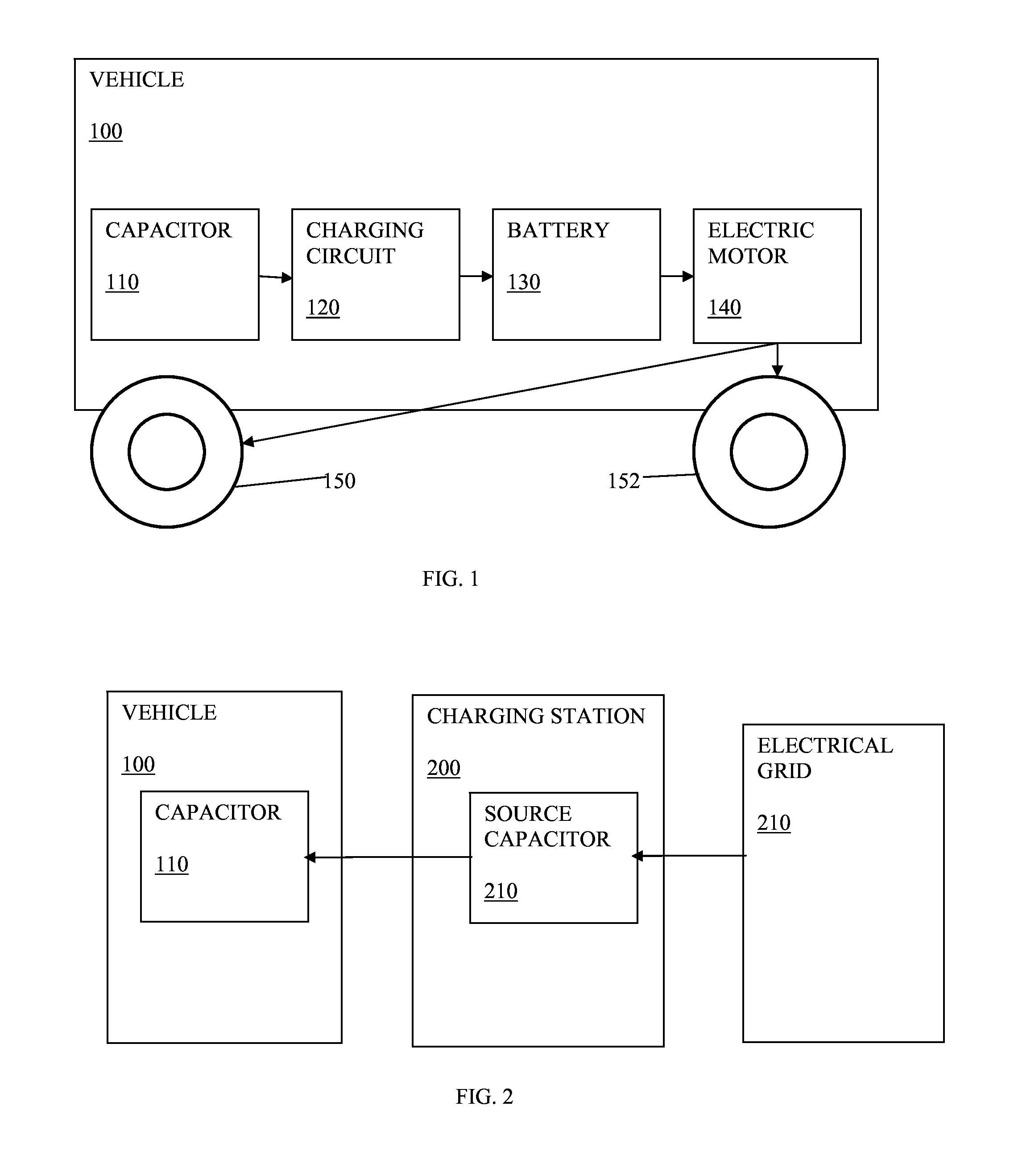
[0031]A large capacity capacitor is installed in a vehicle and adapted to charge a battery in the vehicle through a charging circuit. The charging circuit limits the flow of electricity to the battery to below a maximum charge rate of the battery. The battery stores the electrical energy and drives an electric motor to propel the vehicle.

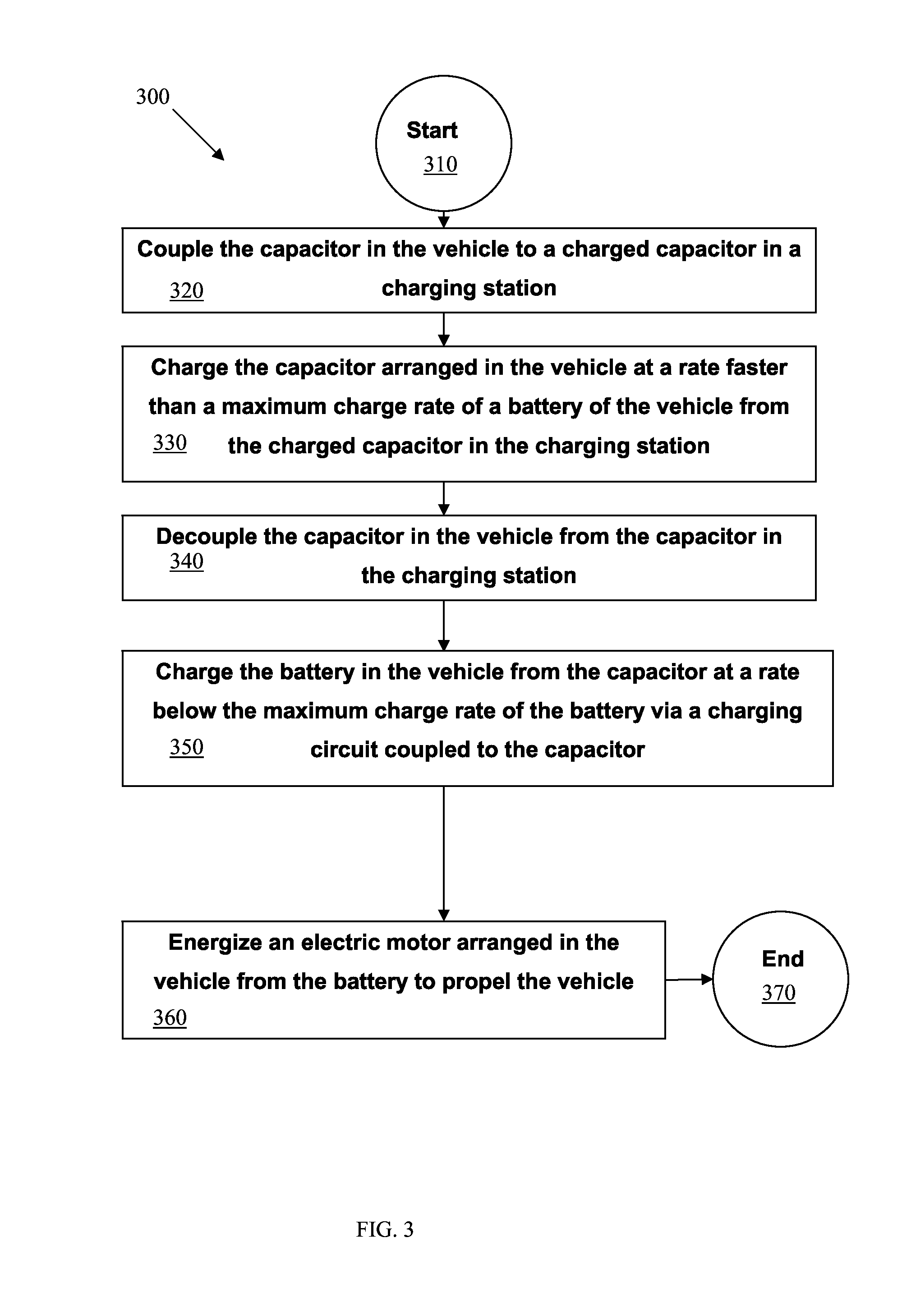
[0032]A capacitor on a vehicle may be quickly charged by a capacitor at a charging station, thereby enabling electric vehicles to increase their range and utility. The charging station may have a similar-sized capacitor that may be electrically coupled to the vehicle's capacitor. The charging station's capacitor may be charged prior to connection to the vehicle capacitor to a charge level selected to cause the charge of the vehicle capacitor to approach without exc...


PUM


Abstract

A vehicle is provided that includes a capacitor situated on the vehicle adapted to be charged by a source separate from the vehicle. The capacitor is adapted to be charged at a rate faster than a maximum charge rate of a battery of the vehicle. The vehicle also includes a charging circuit coupled to the capacitor and adapted to receive electrical charge from the capacitor and regulate the flow of electrical charge below the maximum charge rate of the battery. The vehicle also includes the battery coupled to the charging circuit and adapted to be charged by electrical charge flowing from the capacitor through the charging circuit, and an electric motor adapted to be energized by the battery to propel the vehicle. A method for operating a vehicle is provided that includes charging a capacitor arranged in the vehicle from a source separate from the vehicle.

Description

CROSS-REFERENCE TO RELATED APPLICATIONS[0001]This application claims the benefit of U.S. Provisional Application No. 61 / 402,692 filed Sep. 3, 2010, which is incorporated herein by reference.STATEMENT REGARDING FEDERALLY SPONSORED RESEARCH OR DEVELOPMENT[0002]Not ApplicableBACKGROUND OF THE INVENTION[0003]1. Field of the Invention[0004]The present invention relates to electric vehicles, and in particular relates to a capacitor on a vehicle being rapidly charged by a capacitor at a charging station, and being used to charge a battery in the vehicle, where the battery is used for propulsion of the vehicle.[0005]2. Description of Prior Art[0006]Electric and hybrid vehicles are increasingly popular due to consumer's desires to reduce gas consumption. Electric vehicles typically use a battery or batteries to run an electric motor that drives the wheels. The battery may be recharged a small amount during braking, also referred to as regenerative braking. Batteries may also be charged at a ...

Claims


Application Information

Patent Timeline
Patent Type & Authority Applications(United States)
IPC IPC(8): H02J7/00
CPCB60L11/002Y02T90/163B60L11/185B60L11/1862B60L11/1864B60L2230/16B60L2230/22B60L2230/24B60L2240/545H02J7/345Y02T10/7005Y02T10/7044Y02T10/7061Y02T10/7088Y02T90/121Y02T90/128Y02T90/14B60L11/1816B60L53/14B60L50/90B60L53/11B60L58/21B60L53/305B60L53/51B60L53/52B60L58/15Y02T10/70Y02T10/7072Y02T90/12Y02T90/16
Inventor NEVIN, DONALD M.
Owner NEVIN DONALD M
Learn More