
Relay communication system and first relay server

Active Publication Date: 2012-03-08
MURATA MASCH LTD
View PDF9 Cites 22 Cited by
  • Summary
  • Abstract
  • Description
  • Claims
  • Application Information

AI Technical Summary

Benefits of technology

[0007]Preferred embodiments of the present invention provide a communication method having excellent flexibility and expandability in a communication system in which client terminals communicate with one another through a WAN.
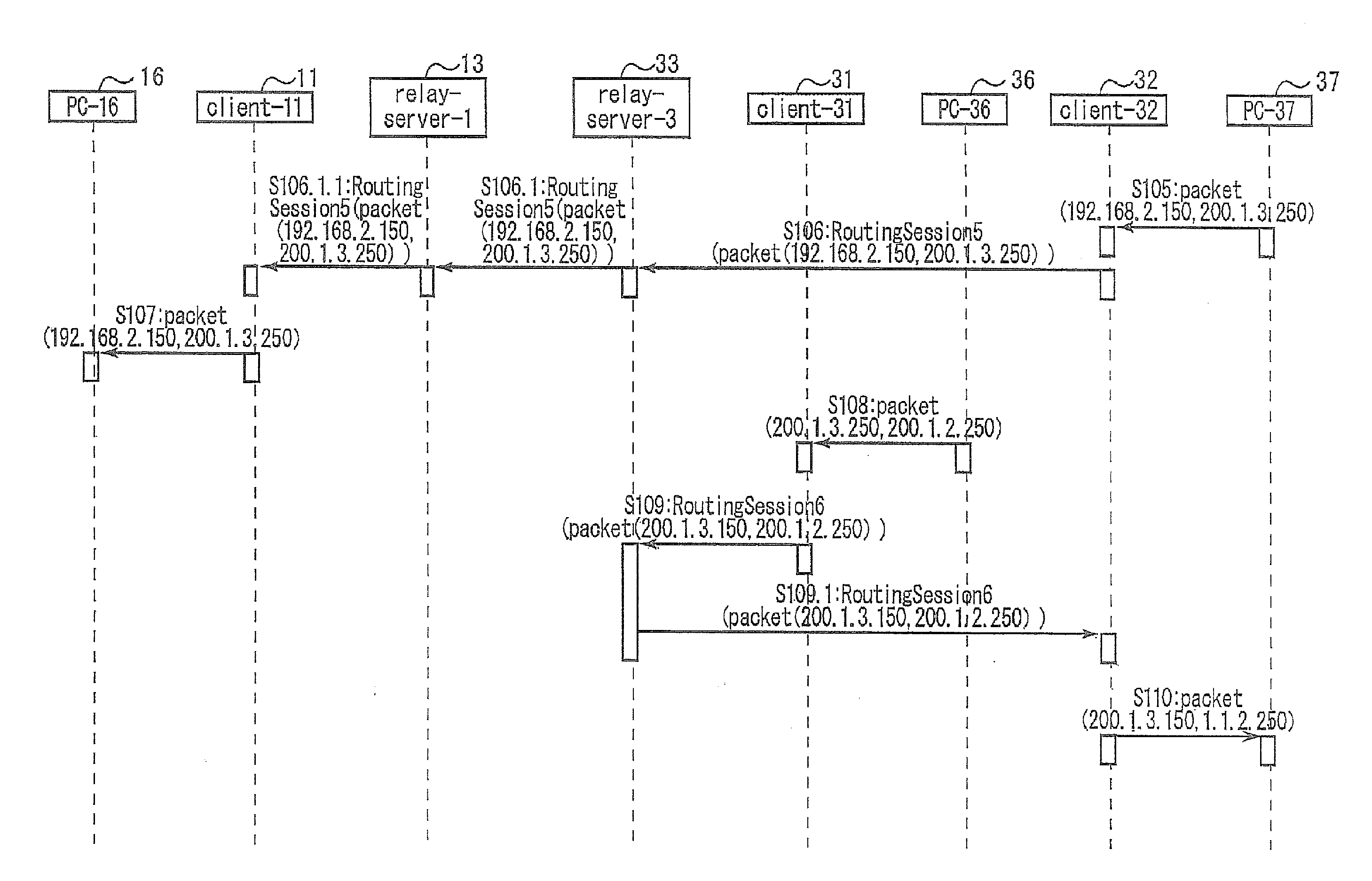
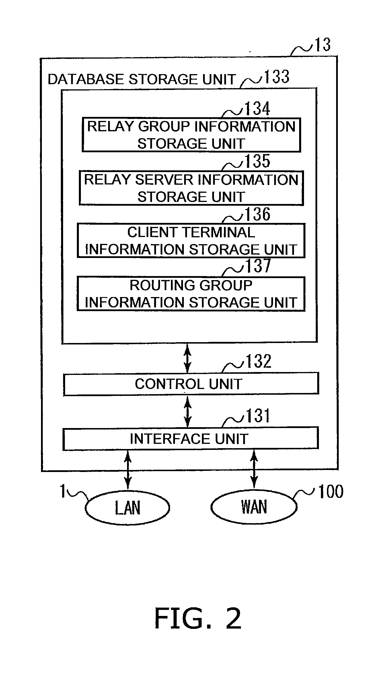
[0021]The relay communication system according to various preferred embodiments of the present invention establishes the routing session between the routing devices based on the routing group information including the network addresses of the LANs and the information regarding the client terminals or the relay servers, which function as the routing devices. By using the routing session, the routing devices execute the routing control for the communication packets transmitted from communication terminals connected to the LAN. By using the routing group information, the client terminals or the relay servers can function as the routing devices, and accordingly, it is possible to flexibly execute the routing control.
[0023]In this manner, the creation of the routing setting information necessary to validate the routing function of the relay communication system is simplified. When the configuration of the relay communication system is changed, it is easy to update the route information, and accordingly, it is easy to manage the routing function using the relay communication system. Moreover, the relay communication system can search for the LAN that can be used for the routing, and based on the search result, can designate the LAN as the routing target. Accordingly, the creation of the routing setting information is further simplified.

Problems solved by technology

However, it is difficult for the VPN to construct a network having expandability and flexibility.

Method used


Image

  • Relay communication system and first relay server
  • Relay communication system and first relay server
  • Relay communication system and first relay server

Examples


Embodiment Construction

1. Entire Configuration of Relay Communication System

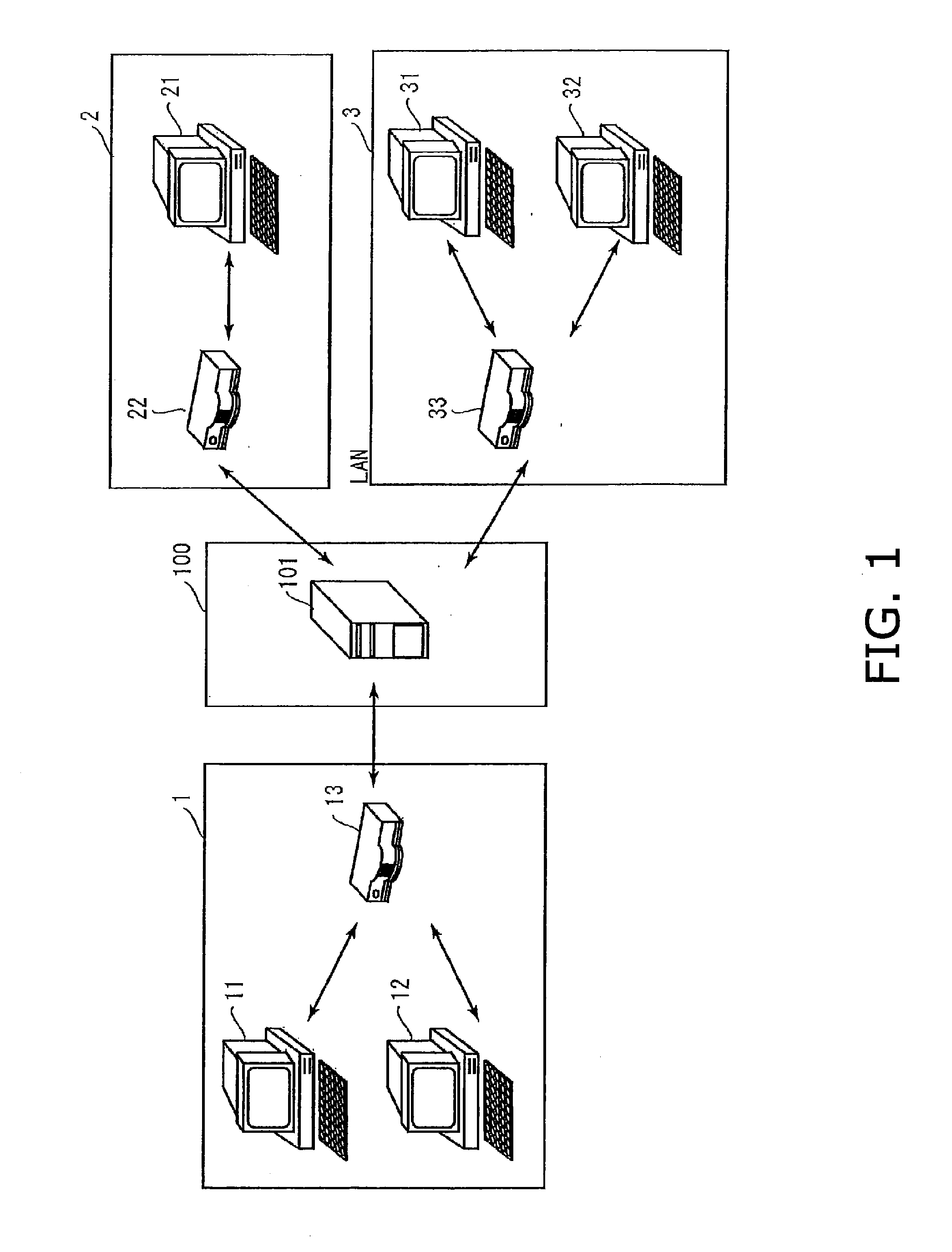
[0070]A description will be provided below of preferred embodiments of the present invention with reference to the drawings. FIG. 1 is a schematic view showing an entire configuration of a relay communication system according to a preferred embodiment of the present invention. The relay communication system includes LANs 1, 2 and 3 and a wide area network (WAN) 100. The WAN 100 is a wide area network, such as the Internet, for example.

[0071]Client terminals 11 and 12 and a relay server 13 are connected to the LAN 1. A client terminal 21 and a relay server 22 are connected to the LAN 2. Client terminals 31 and 32 and a relay server 33 are connected to the LAN 3. A session initiation protocol (SIP) server 101 is connected to the WAN 100.

[0072]The client terminals individually connected to the LANs 1 to 3 are preferably personal computers or other suitable devices, for example. The relay servers 13, 22 and 33 relay communication betw...


PUM


Abstract

A relay communication system includes a first client terminal which creates routing group information including network addresses of first and second LANs, and identification information of the first client terminal and a second client terminal which execute routing processing, and which shares the routing group information with the second client terminal. Based on the routing group information, a routing session is established between the first and second client terminals. A communication terminal connected to the first LAN sends out a communication packet in which an IP address of a communication terminal connected to the second LAN is designated. The communication packet is encapsulated by the first client terminal, and is routed by using the routing session.

Description

BACKGROUND OF THE INVENTION[0001]1. Field of the Invention[0002]The present invention relates to a relay communication system that enables client terminals connected to local area networks (LANs) to communicate with one another beyond a wide area network (WAN).[0003]2. Description of the Related Art[0004]By using a virtual private network (VPN), a client terminal can communicate with another client terminal remotely located beyond a WAN. However, it is difficult for the VPN to construct a network having expandability and flexibility.[0005]A relay communication system disclosed in Japanese Patent Laid-Open Publication No. 2008-129991 can construct a network which appears as if remote LANs were directly connected to one another in a similar way to the VPN. This relay communication system is superior in terms of expandability and flexibility to the general VPN in that it is possible to dynamically change a group relationship among the LANs, and so on.[0006]In the relay communication sy...

Claims


Application Information

Patent Timeline
IPC IPC(8): H04L12/56
CPCG06F2213/0038H04L41/0893H04L45/02H04L45/66H04L67/28H04L12/28H04L12/46H04L12/4604H04L12/4641G06F13/00H04L67/56
Inventor TANIMOTO, YOSHIFUMI
Owner MURATA MASCH LTD
Learn More