Tilted gratings and method for production of tilted gratings

Active Publication Date: 2012-03-08
KONINKLIJKE PHILIPS ELECTRONICS NV
View PDF4 Cites 33 Cited by
  • Summary
  • Abstract
  • Description
  • Claims
  • Application Information

AI Technical Summary

Benefits of technology

[0007]It may be desirable to have an imaging system p

Problems solved by technology

However, in particular in the case of cone-beam geometry, strong phase-contrast

Method used


Image

  • Tilted gratings and method for production of tilted gratings
  • Tilted gratings and method for production of tilted gratings
  • Tilted gratings and method for production of tilted gratings

Examples


Embodiment Construction

[0070]The illustration in the drawings is schematically and not to scale. In different drawings, similar or identical elements are provided with the same reference numerals.

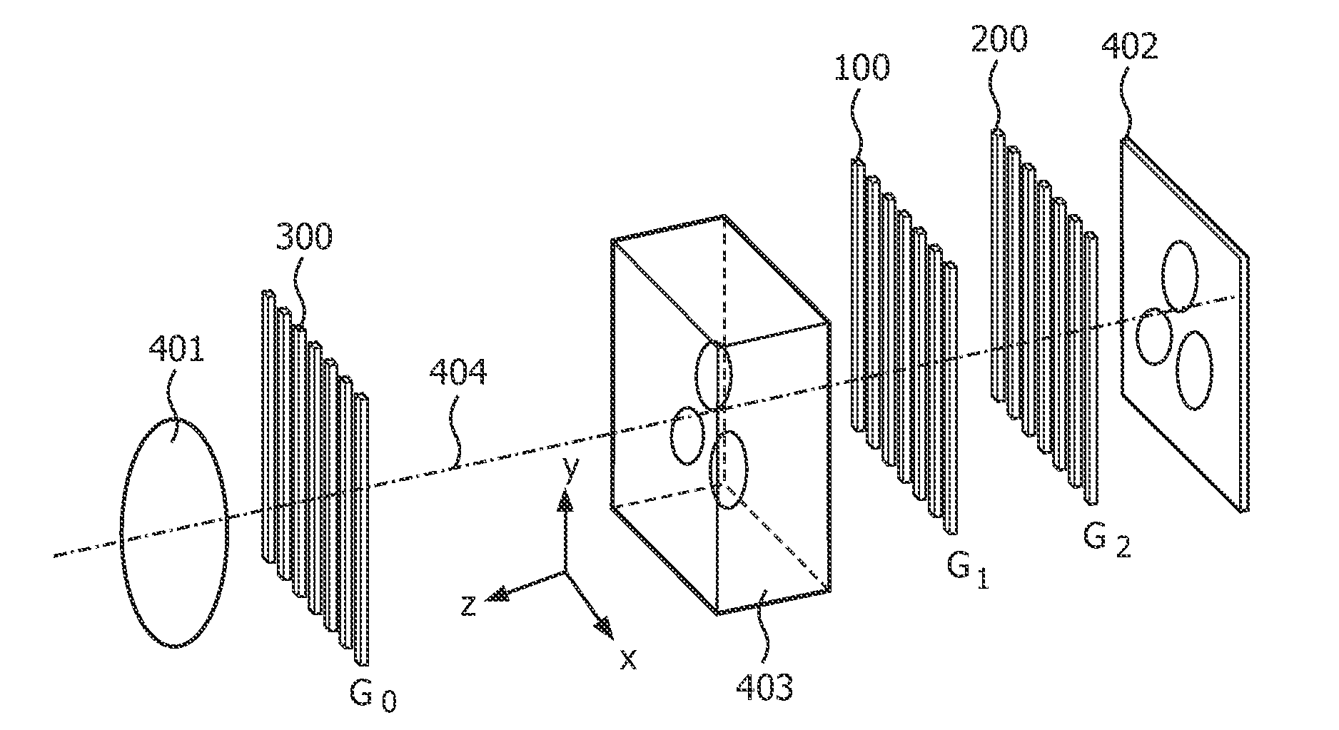
[0071]FIG. 1A shows a measurement setup for differential phase-contrast imaging (DPCI setup). The imaging apparatus comprising a source of electromagnetic radiation, for example an X-ray source or an optical source, symbolized by the focal spot 401. After the source, an absorption or source grating 300 (G0) is arranged for spatial beam coherence. The incoherent X-ray source used is symbolized by the focal spot 401. The radiation beam emitted by the source has an optical axis 404. First, the beam passes the absorption grating 300. Then, the beam passes the object of interest 403 and then the phase grating 100 (G1). After that, the beam passes a second absorption grating 200 (G2), which is arranged before the imaging detector 402.

[0072]The phase grating 100 is adapted for producing an interference pattern between G...


PUM


Abstract

The present invention relates to phase-contrast imaging which visualizes the phase information of coherent radiation passing a scanned object. Focused gratings are used which reduce the creation of trapezoid profile in a projection with a particular angle to the optical axis. A laser supported method is used in combination with a dedicating etching process for creating such focused grating structures.

Description

FIELD OF THE INVENTION[0001]The invention relates to phase-contrast imaging. In particular, the invention relates to a grating for a phase-contrast imaging apparatus, a phase-contrast imaging apparatus comprising such a grating, and a method of fabricating a grating for a phase-contrast imaging apparatus.BACKGROUND OF THE INVENTION[0002]For examination of objects of interest with electromagnetic radiation, visible or invisible light or X-rays may be used. X-ray differential phase-contrast imaging (DPCI) visualizes the phase information of coherent X-rays passing a scanned object. In addition to classical X-ray transmission imaging, DPCI determines not only the absorption properties of a scanned object along a projection line, but also the phase shift of the transmitted X-rays, and thus provides variable additional information usable for contrast enhancement, material composition or dose reduction.[0003]Recently, a group at Paul-Scherrer Institute, Villingen, Switzerland has introduc...

Claims


Application Information

Patent Timeline
IPC IPC(8): G21K1/06B29D11/00G02B5/18
CPCG02B5/1857A61B6/484G21K2207/005G21K2201/06
Inventor VOGTMEIER, GEREONENGEL, KLAUS JUERGENKOEHLER, THOMASROESSL, EWALD
Owner KONINKLIJKE PHILIPS ELECTRONICS NV
Why Eureka
Try Eureka