Assembled battery

a battery and assembly technology, applied in the field of assembly batteries, can solve problems such as difficulty in maintenance or the like, and achieve the effects of reducing weight, reducing short-circuiting, and adjusting the pressing force minutely and easily

Inactive Publication Date: 2012-03-08
MITSUBISHI HEAVY IND LTD
View PDF2 Cites 19 Cited by
  • Summary
  • Abstract
  • Description
  • Claims
  • Application Information

AI Technical Summary

Benefits of technology

[0014]Further, the terminal connection member may include an insulating portion that coats at least a part of an outer surface of the conductor and the opposite conductive wall. Accordingly, it is possible to suppress short-circuiting caused by the contact of foreign matter.
[0015]Further, the elastic portion may be formed as a member separated from the opposite conductive wall. Accordingly, it is possible to minutely and easily adjust the pressing force by changing the elastic portion.
[0016]Further, the electrode terminal may be formed in a flat plate shape and has a first hollow formed on the plate surface thereof, and the terminal connection member may include a spherical body provided at the front end of the elastic portion and fitted to the first hollow. Accordingly, the electrode terminal and the terminal connection member are locked to each other by the fitting between the first hollow and the spherical body, so that the electrode terminal and the terminal connection member may be further reliably prevented from being separated from each other.
[0017]Further, the electrode socket may be divided into two parts in a direction intersecting the protruding direction of the electrode terminal, one of two parts may include the opposite conductive wall, and the other of two parts may be formed to have elasticity and serves as the elastic portion. Accordingly, since the structure becomes simple, it is possible to decrease the weight or improve the maintenance workability.
[0018]Further, the electrode terminal may be formed in a cylindrical shape and have a circumferential groove formed at the outer peripheral surface thereof, and the terminal connection member may include a claw portion protruding from each of the electrode sockets and fitted to this groove. Accordingly, the electrode terminal and the terminal connection member are locked to each other by the fitting between the groove and the claw portion, so that the electrode terminal and the terminal connection member may be further reliably prevented from being separated from each other.
[0019]According to the assembled battery of the aspect of the invention, it is possible to keep the low contact resistance and make attachment and detachment easier.

Problems solved by technology

However, in the related art, since it takes time and effort in the work of attachment and detachment of the connections for each electrode terminal and each clip portion through metal bonding, there is a possibility that when there is a failure, maintenance or the like is difficult.

Method used


Image

  • Assembled battery
  • Assembled battery
  • Assembled battery

Examples


first embodiment

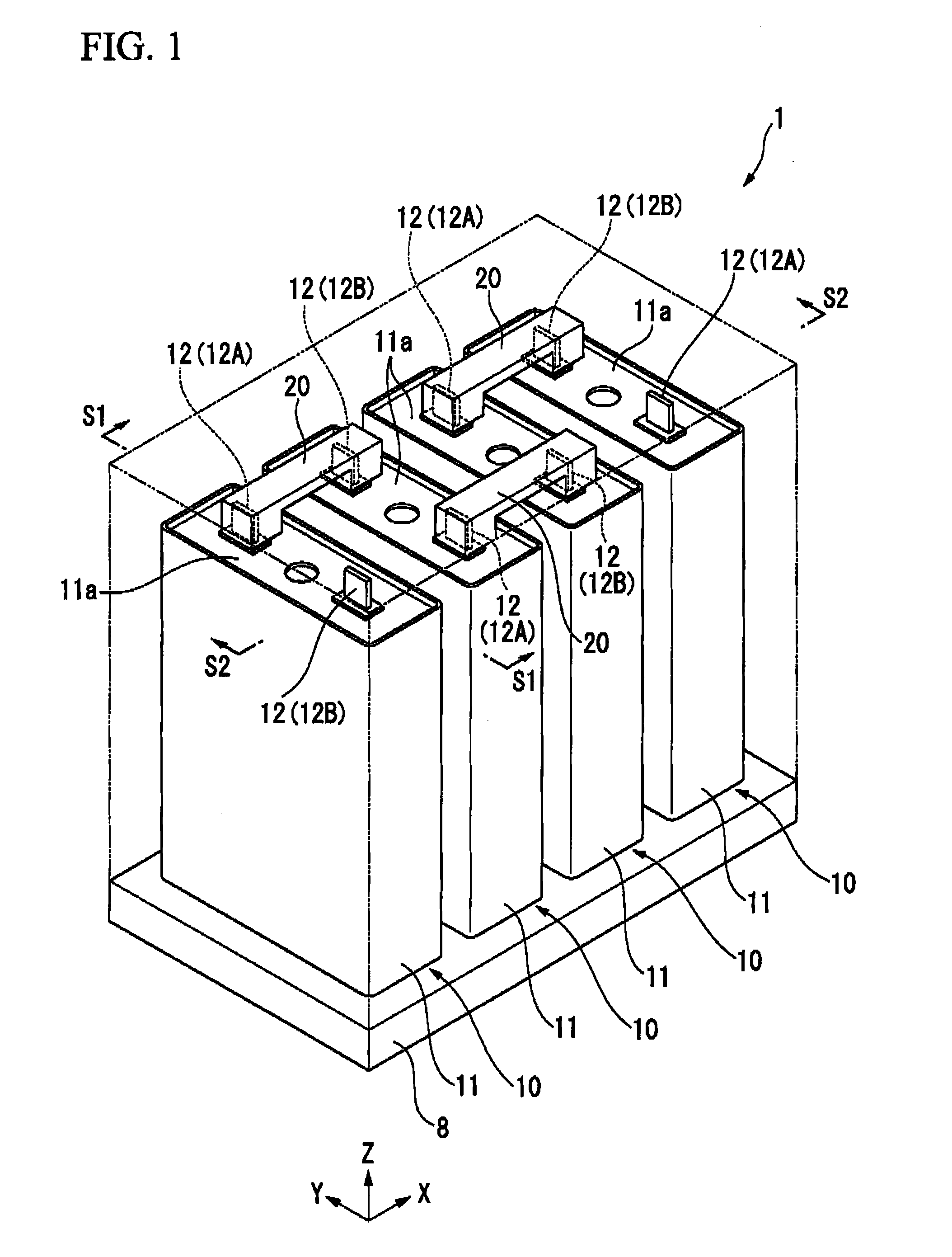
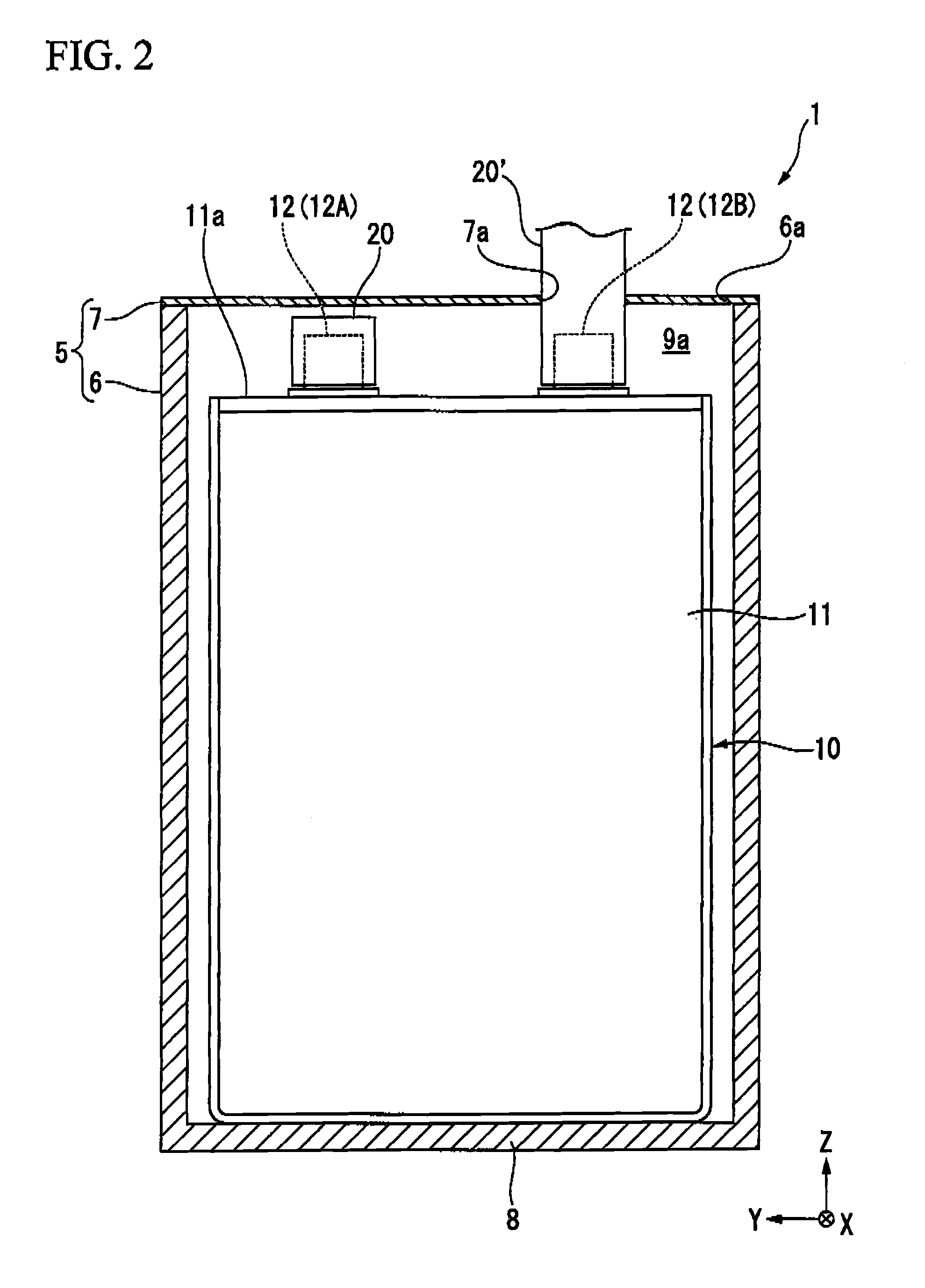
[0029]FIG. 1 is a perspective view illustrating an assembled battery 1 according to a first embodiment of the invention, FIG. 2 is a cross-sectional view taken along the line S1-S1 of FIG. 1, FIG. 3 is a cross-sectional view taken along the line S2-S2 of FIG. 1, and FIG. 4 is a cross-sectional view taken along the line S3-S3 of FIG. 3.

[0030]As shown in FIG. 1, the assembled battery 1 includes a plurality of electrical cells 10 that are chargeable / dischargeable. It means that they are secondary batteries. The assembled battery 1 is used as a power supply of a battery system, for example, a power supply driving a mobile object such as a deep-sea research vehicle or an electrical vehicle or a power supply provided in a stationary device such as a power storage device or a UPS device.

[0031]Furthermore, in the description below, the longitudinal direction of the assembled battery 1 is set as the X direction, the lateral direction of the assembled battery 1 is set as the Y direction, and ...

second embodiment

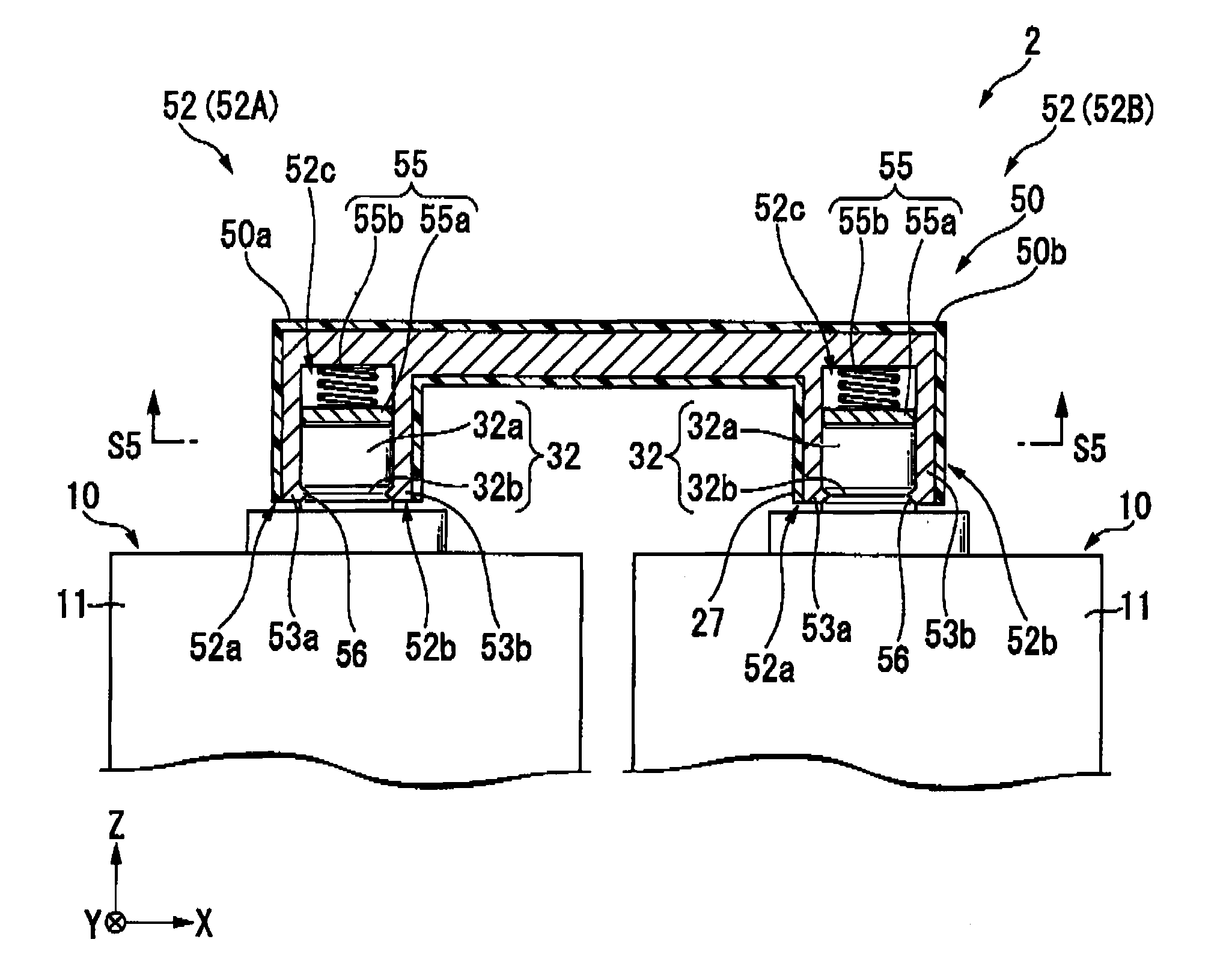
[0073]FIG. 6 is a perspective view illustrating a main part of an assembled battery 2 according to a second embodiment of the invention, FIG. 7 is a cross-sectional view taken along the line S4-S4 of FIG. 6, and FIG. 8 is a cross-sectional view taken along the line S5-S5 of FIG. 7. Furthermore, in FIGS. 6 to 8, the same reference numerals are given to the same components as those of FIGS. 1 to 5, and the components will not be repetitively described here.

[0074]As shown in FIG. 6, the assembled battery 2 is different from the above-described assembled battery 1 in that a cylindrical electrode terminal 32 is provided compared to the plate-shaped electrode terminal 12 of the electrical cell 10 of the assembled battery 1, and in that a terminal connection member 50 is used instead of the terminal connection member 20.

[0075]As shown in FIG. 6, the electrode terminal 32 is formed in a cylindrical shape, and extends to the +Z direction. The electrode terminal 32 includes a circumferential ...


PUM

PropertyMeasurementUnit
conductiveaaaaaaaaaa
elasticityaaaaaaaaaa
cylindrical shapeaaaaaaaaaa

Abstract

An assembled battery includes: a plurality of electrical cells that includes a battery body and an electrode terminal protruding from the battery body; and a terminal connection member that connects a pair of electrode terminals between two of the plurality of electrical cells, wherein the terminal connection member includes: a pair of electrode sockets each allowing the electrode terminal to be inserted thereinto, and a conductor electrically connecting the pair of electrode sockets to each other, and wherein each electrode socket includes: an opposite conductive wall extending from the conductor along the electrode terminal and facing the electrode terminal, and an elastic portion provided at a position facing the opposite conductive wall toward the electrode terminal and pressing the electrode terminal to the opposite conductive wall.

Description

BACKGROUND OF THE INVENTION[0001]1. Field of the Invention[0002]The present invention relates to an assembled battery.[0003]Priority is claimed on Japanese Patent Application No. 2010-198150, filed on Sep. 3, 2010, the content of which is incorporated herein by reference.[0004]2. Description of Related Art[0005]It is widely known that a rechargeable secondary battery has been used in fields such as an electrical vehicle, a power storage system, and an uninterruptible power system (UPS). In the exemplified field, since the power supply capacity is several ten thousand Wh, an assembled battery is generally used in which a plurality of electrical cells is connected in series or in parallel to each other.[0006]In such an assembled battery, for example, a positive electrode terminal of an electrical cell, and a negative electrode terminal of an electrical cell located right next to the electrical cell having the positive electrode terminal, are connected to each other through a terminal ...

Claims


Application Information

Patent Timeline
Patent Type & Authority Applications(United States)
IPC IPC(8): H01M2/24H01M50/529H01M50/503H01M50/507H01M50/514H01M50/526
CPCH01M2/202H01M2/206H01M2/204Y02E60/10H01M50/507H01M50/514H01M50/526H01M50/503
Inventor HASHIZAKI, KATSUO
Owner MITSUBISHI HEAVY IND LTD
Why Eureka
Try Eureka