
Blasting apparatus and method for blast processing

Inactive Publication Date: 2012-03-08
SHARP KK
View PDF33 Cites 5 Cited by
  • Summary
  • Abstract
  • Description
  • Claims
  • Application Information

AI Technical Summary

Benefits of technology

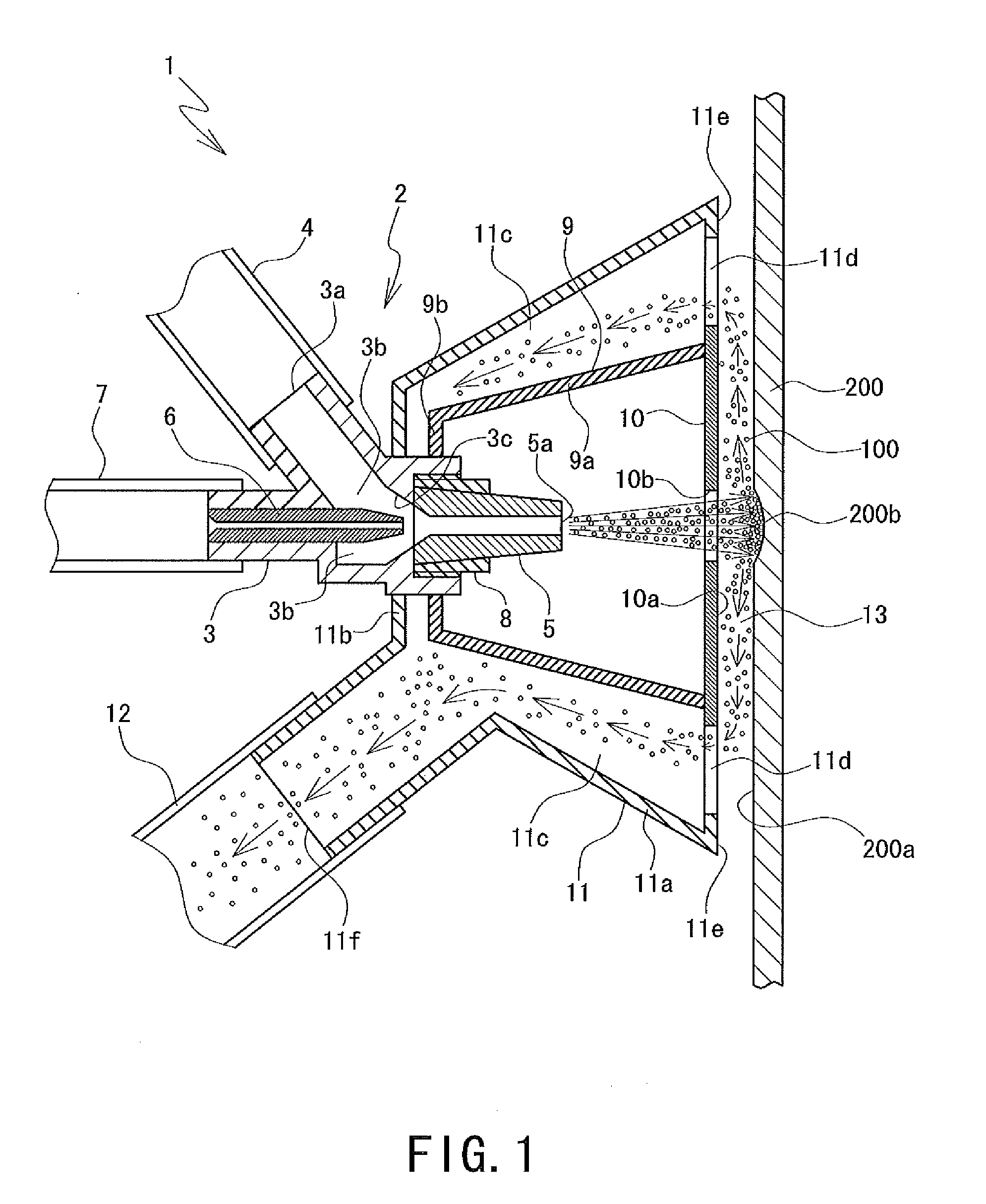
[0022]According to the blasting apparatus and the method for blast processing according to the preferred embodiments of the present invention, a scattering force of the abrasive (a force of the abrasive scattering around) used for blast processing the work surface can be abated more as the abrasive scatters farther in the clearance provided between the surface for airflow alignment of the cover and the work surface, and the abrasive can be collected by suction from the collecting passage provided to the collecting case. Thus, the blasting apparatus and the method for blast processing are capable of preventing the suction power from influencing the striking power of strikes of the abrasive on the work surface even when the suction power from the collecting passage is increased so that the abrasive, even having a small grain diameter, may be sufficiently sucked. In addition, the blasting apparatus and the method for blast processing are capable of maintaining blast processing accuracy, and collecting the abrasive while preventing the abrasive from scattering around.

Problems solved by technology

If there exists such a defect, a problem that causes a scattering of light arises.
The defect is scraped off the glass substrate in a method using a blasting apparatus for processing the glass substrate, in which the glass substrate is struck with a high-speed blast of an abrasive (also referred to a shot or an abrasive grain) such as alumina powder, silicon carbide powder, glass beads and very small steel balls, together with fluid such as air, and the striking power causes minute destruction to the glass substrate to process the glass substrate.
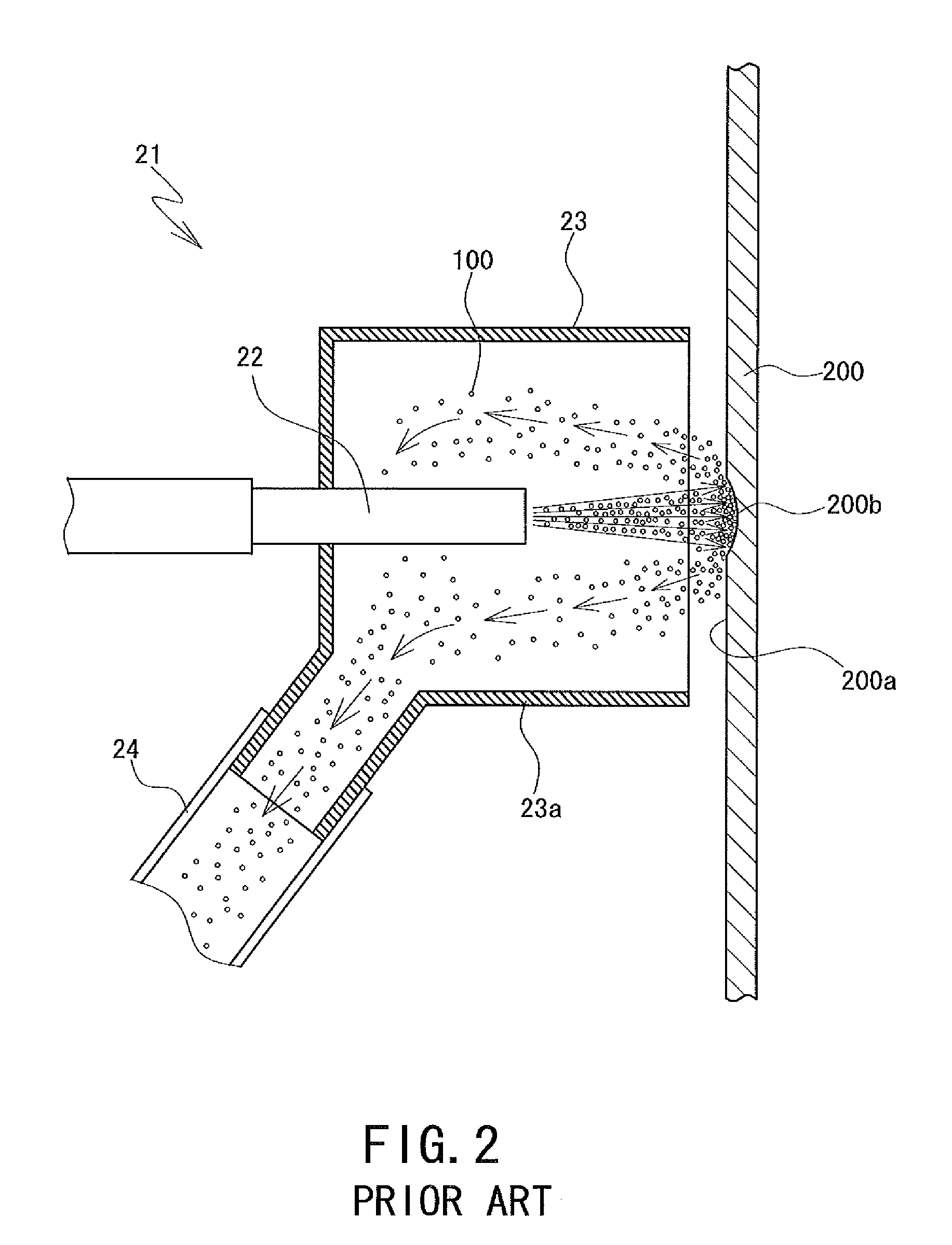
The abrasive 100 is collected because, while shattering around, it worsens a working environment and exert a harmful influence such as health damage on workers.

Method used


Image

  • Blasting apparatus and method for blast processing
  • Blasting apparatus and method for blast processing
  • Blasting apparatus and method for blast processing

Examples


Embodiment Construction

[0025]A detailed description of a blasting apparatus and a method for blast processing according to preferred embodiments of the present invention will now be provided with reference to the accompanying drawings.

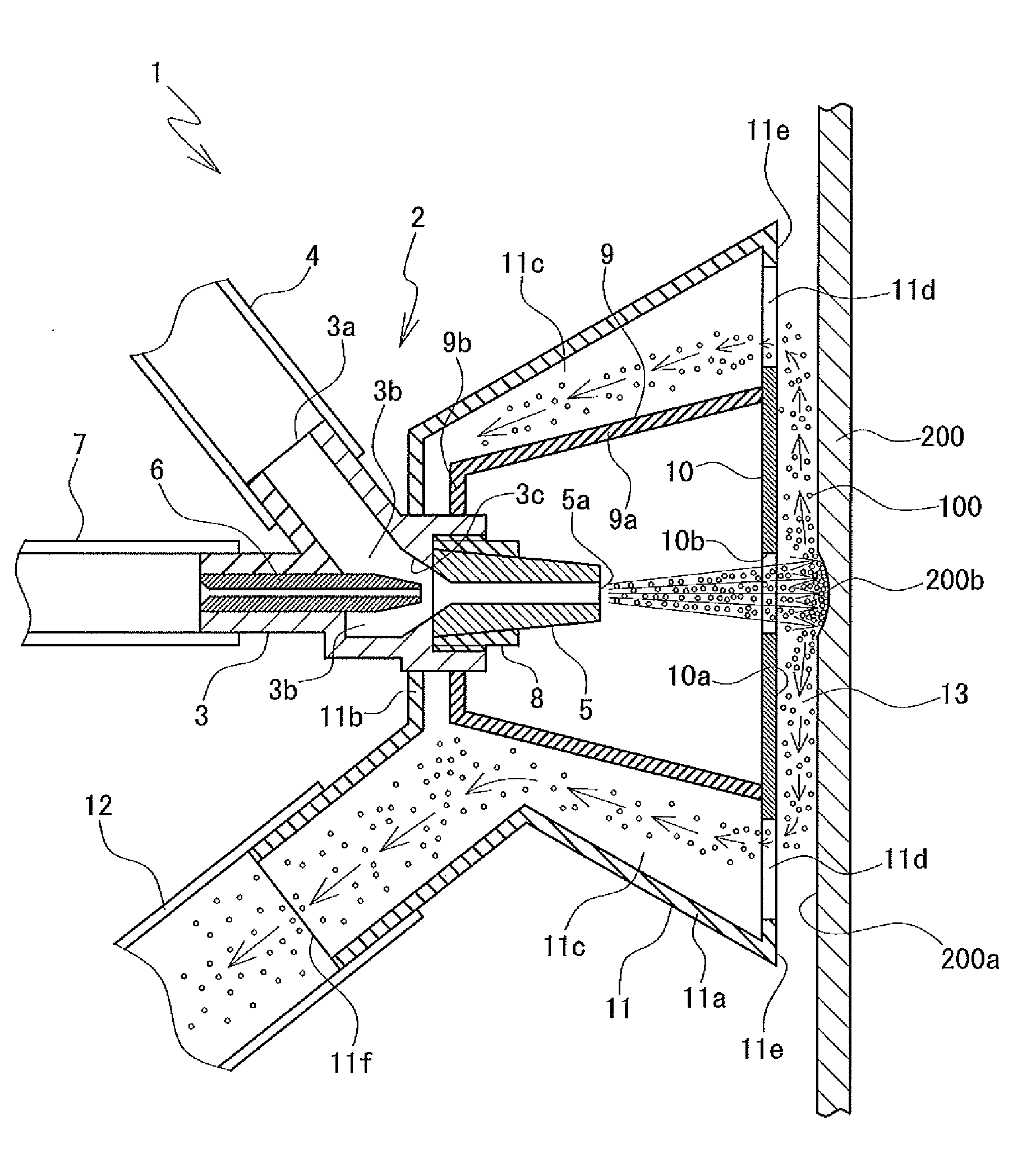
[0026]FIG. 1 is a cross-sectional view showing a schematic configuration of a blasting apparatus 1 according to one of the preferred embodiments of the present invention. The blasting apparatus 1 includes a blasting nozzle 2. The blasting nozzle 2 includes a nozzle body 3 that includes a port 3a for abrasive feeding and a chamber 3b for abrasive guiding that communicates with the port 3a and has the shape of a cylindrical container, where an abrasive 100 is guided to the chamber 3b via a hose 4 for abrasive supply from a tank for abrasive supply (not shown) as shown in FIG. 1. The chamber 3b includes a conical inner surface 3c disposed at the front end of the chamber 3b.

[0027]The front end of a pipe 6 for air blasting that is inserted from behind the chamber 3b is disposed ...


PUM


Abstract

A blasting apparatus capable of increasing suction power to collect an abrasive without exerting any influence on processing of a work surface with the abrasive. The apparatus includes a blasting nozzle (2) blasting an abrasive (100) on a surface (200a) of work (200), a cover (10) including a surface (10a) for airflow alignment parallel to the work surface and a blast hole (10b) through which the abrasive from the nozzle passes, a nozzle case (9) including the cover and surrounding the nozzle, and a collecting case (11) covering an outer surface of the nozzle case and including a collecting passage (11c) disposed around the nozzle case, from the passage, the abrasive being collected by suction, wherein the apparatus collects the abrasive that is blasted from the nozzle and strikes the work surface from the passage through a clearance (13) provided between the airflow-alignment surface and the work surface.

Description

TECHNICAL FIELD[0001]The present invention relates to an apparatus and a method for processing a surface of work, and specifically relates to a blasting apparatus and a method for blast processing, with which processing is performed such that a depressed portion is formed on a surface of work such as a glass substrate by the use of a blast of an abrasive.BACKGROUND ART[0002]Conventionally, a glass substrate having a thickness of about 0.7 mm is generally used for a flat-screen display panel such as a liquid crystal display panel and a plasma display panel. The glass substrate of this type is desired to have a flat surface and an excellent light transmission property.[0003]The glass substrate of this type could sometimes develop, during production, a defect such as a tiny flaw and a pore of air bubble on its surface, or a defect such as an air bubble and a foreign substance that are trapped inside of the glass substrate. If there exists such a defect, a problem that causes a scatteri...

Claims


Application Information

Patent Timeline
IPC IPC(8): B24C1/00B24C9/00
CPCB24C9/003B24C5/02
Inventor YOSHIZAWA, TAKENORISAWAI, KAZUTERU
Owner SHARP KK
Learn More