System Comprising a Box for Implanting in a Body Part

a body part and box technology, applied in the direction of head electrodes, internal electrodes, therapy, etc., can solve the problems of undesired burr hole loading and patient skull loading

Active Publication Date: 2012-03-08
MEDTRONIC BAKKEN RES CENT
View PDF3 Cites 26 Cited by
  • Summary
  • Abstract
  • Description
  • Claims
  • Application Information

AI Technical Summary

Benefits of technology

[0004]It is an object of the invention to provide a system of the kind defined in the opening paragraph, wherein forces exerted on the mamal body part during inserting the module into the box are reduced.

Problems solved by technology

A disadvantage of the generator disclosed in US-A 2007 / 0225773 A1 is in the fact that mounting the dome to the transcranial insert exerts forces on said insert and will consequently load the burr hole in the patient's skull.
This loading of the burr hole is undesired given a burr hole's vulnerable nature.

Method used


Image

  • System Comprising a Box for Implanting in a Body Part
  • System Comprising a Box for Implanting in a Body Part
  • System Comprising a Box for Implanting in a Body Part

Examples


Embodiment Construction

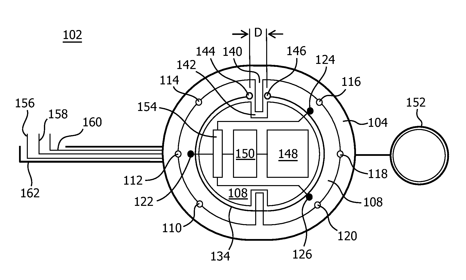
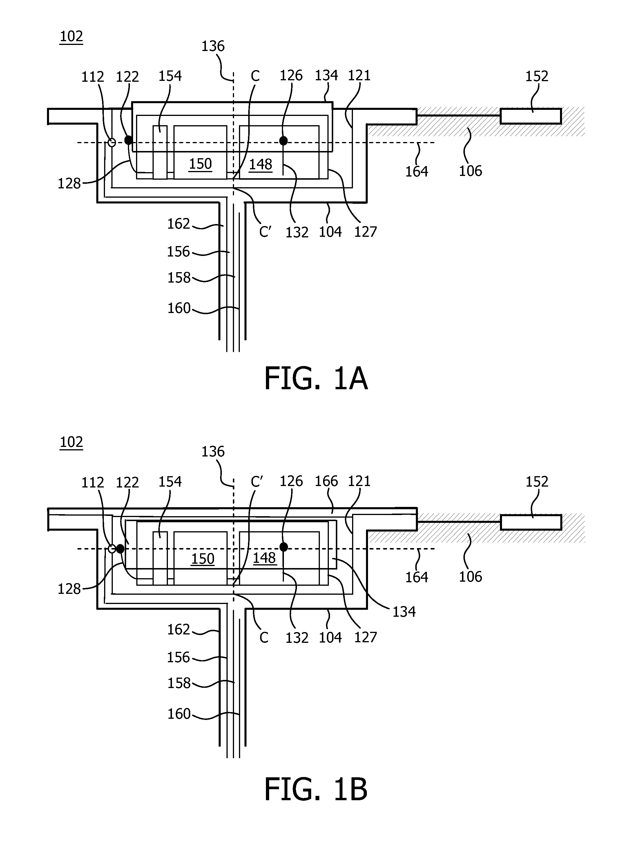
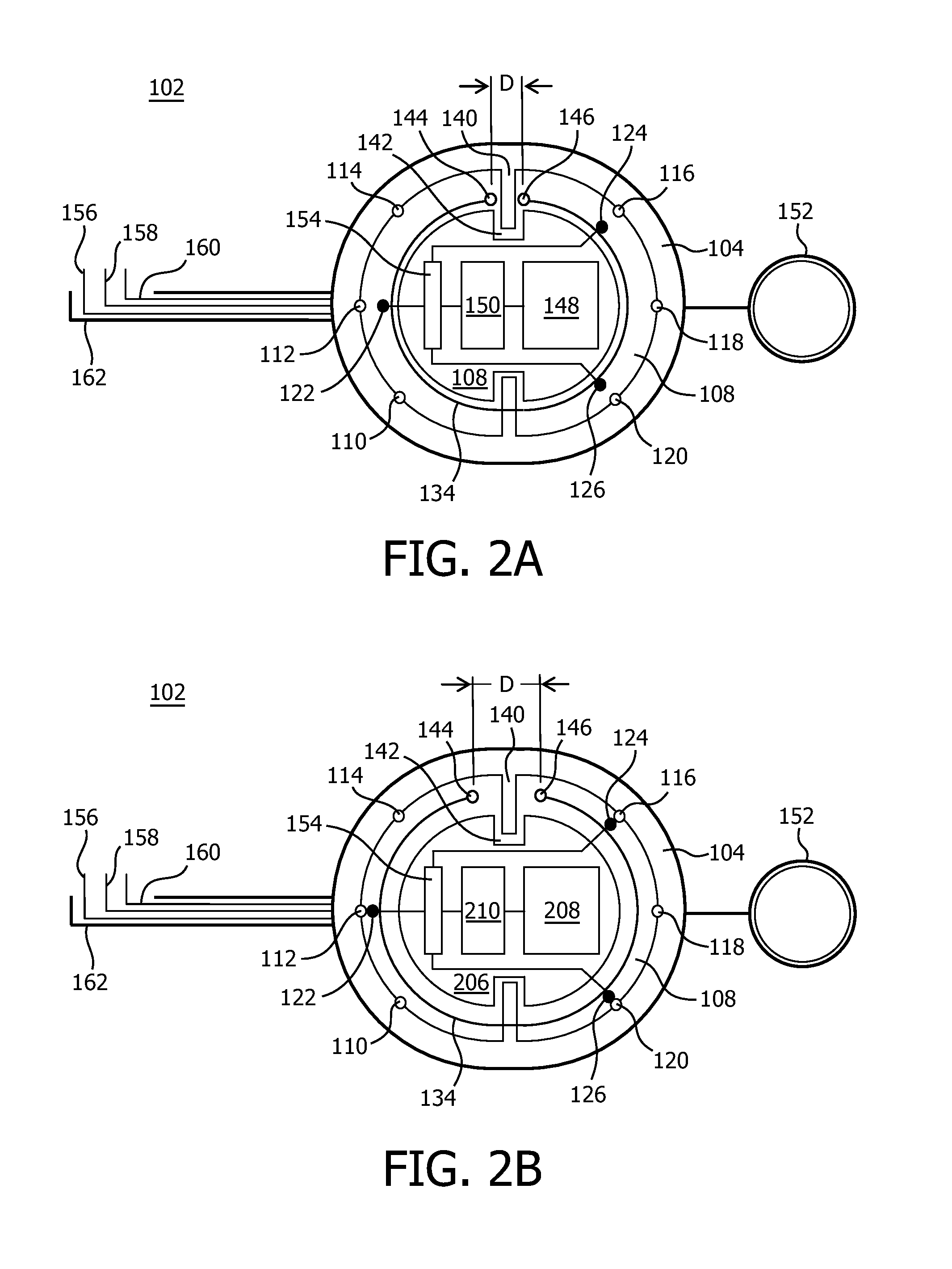
[0035]FIG. 1A schematically displays a cross-sectional view of a system 102, which system is configured for electrically stimulating a brain. The system 102 comprises a box 104 for implanting in a body part 106, and a module 108 for accommodating in the box 104. In FIG. 1A, the module 108 is situated in a stationary accommodation in the box 104. Herein, the module is accommodated into the box along an axis 136, which axis 136 vertically passes through a geometrical center C of the module 108. In this example, both the box 104 and the module 108 are made from titanium, a.o. for its excellence resistance to corrosion. The box 102 is provided with a first set of electrical contacts comprising a first electrical contact 110 and first electrical contacts 112, 114, 116, 118 and 120, which are depicted in FIG. 2A.

[0036]Referring to FIG. 1A, the first electrical contacts 110, 112, 114, 116, 118 and 120 are mounted on an interior 121 of the box 104. Further, the first electrical contacts 110...


PUM


Abstract

A system (102) comprising a box (104) for implanting in a mamMal body part (106), which box is provided with a first electrical contact (110, 121, 114, 116, 118, 120), and a module (108) for accommodating in the box, which module is provided with a second electrical contact (122, 124, 126) for cooperation with said first electrical contact. The first electrical contact and the second electrical contact are mutually movable, at least in a stationary accommodation of the module in the box, between a contact position in which said first and second electrical contacts are electrically connected, and a non-contact position in which said first and second electrical contacts are separated from each other.

Description

FIELD OF THE INVENTION[0001]The invention relates to a system comprising a box implantable in a mammal body part and a module accommodatable in the box.BACKGROUND OF THE INVENTION[0002]In US-A 2007 / 0225773 A1, an implantable transcranial pulse generator for generating neuro-modulating electrical signals is disclosed. The generator according to US-A 2007 / 0225773 A1 comprises transcranial insert for mounting within a burr hole located in a skull of the patient, and a dome removably mounted to the transcranial insert. The dome and the insert contain electronic components and have complementary connectors facilitating direct electrical interconnection.[0003]A disadvantage of the generator disclosed in US-A 2007 / 0225773 A1 is in the fact that mounting the dome to the transcranial insert exerts forces on said insert and will consequently load the burr hole in the patient's skull. Namely, a friction force present between the complementary connectors for facilitating direct electrical inter...

Claims


Application Information

Patent Timeline
Patent Type & Authority Applications(United States)
IPC IPC(8): A61N1/00
CPCA61N1/0529A61N1/375A61N1/37229A61N1/0539A61N1/37514A61N1/37518
Inventor PARDOEL, MICHEL G.DECRE, MICHEL M.J.MARTENS, HUBERT C.F.BUDZELAAR, FRANCISCUS P.M.GOOTZEN, JOZEF F.E.TOL, JEROEN J.A.
Owner MEDTRONIC BAKKEN RES CENT
Why Eureka
Try Eureka