
Garden shears

a shear and garden technology, applied in the field of garden shears, can solve the problems of unbalanced stresses, increased effort, and difficulty in cutting motion, and achieve the effect of improving the reflective structur

Active Publication Date: 2012-03-15
HO CHENG GARDEN TOOLS
View PDF8 Cites 16 Cited by
  • Summary
  • Abstract
  • Description
  • Claims
  • Application Information

AI Technical Summary

Benefits of technology

[0007]An objective of the present invention is to provide an improved reflective structure.
[0008]Another objective of the present invention is to provide an improved reflective structure that is relatively thinner and capable of covering the entire object surface for better reflection effects.
[0009]Another objective of the present invention is to provide an improved reflective structure that can improve the safety of the bicycle for riders at night.
[0011]With the above-mentioned garden shears, the following benefits can be obtained: 1. The major and minor cutting members both respectively have an applying arm; when a counterforce is generated because of the applied force, the counterforce is evenly distributed across the applying arm instead of being concentrated on a single side, which would otherwise create difficulties in operation. 2. Since the screws move along the limiting slots a maximum opening angle between the tool ends is limited; the user does need to waste time to close the tool ends. Furthermore, the range of the limiting slots corresponds to the usable range of the garden shears, so that the tool ends are not separated by too narrow an angle, which would otherwise lead to difficulties in operation. 3. Each of the major and minor cutting members is engaged with one applying arm, such that it is easy to operate and the application force is evenly distributed on both sides.

Problems solved by technology

However, the prior art structure has the following drawbacks: 1. The first member 70 and the second member 80 are both disposed on the same side of the metal lever 60; when the cutting motion is performed and a counterforce is generated, the counterforce is concentrated at the engaging area of the first member 70 and the second member 80 and is not evenly dispersed over both sides; therefore, the cutting motion is affected by the unbalanced stresses and is made more difficult.
Furthermore, when the first and second members 70, 80 are too far apart, more effort is required to close them which is very inconvenient for users.

Method used


Image

  • Garden shears
  • Garden shears
  • Garden shears

Examples


Embodiment Construction

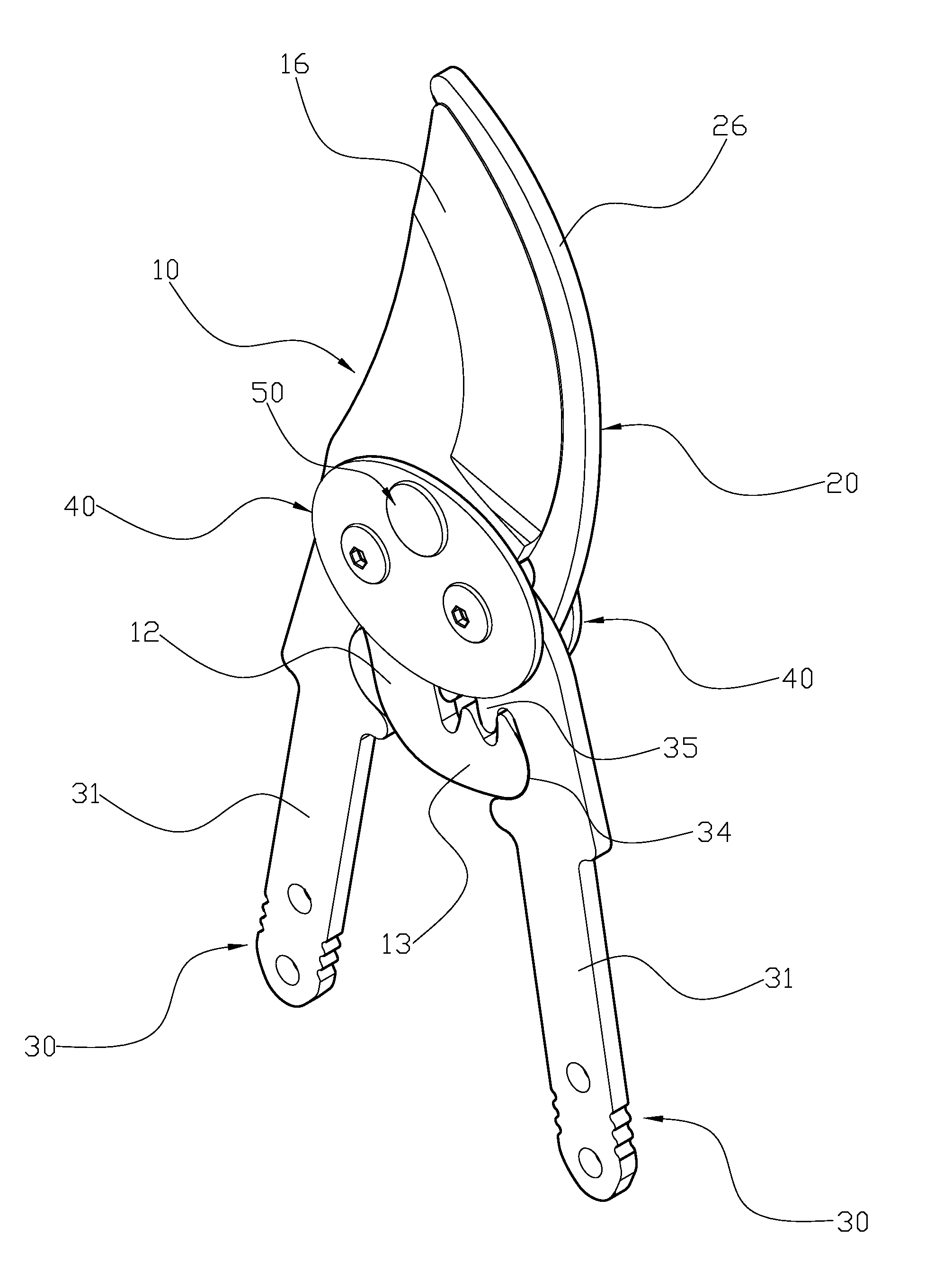
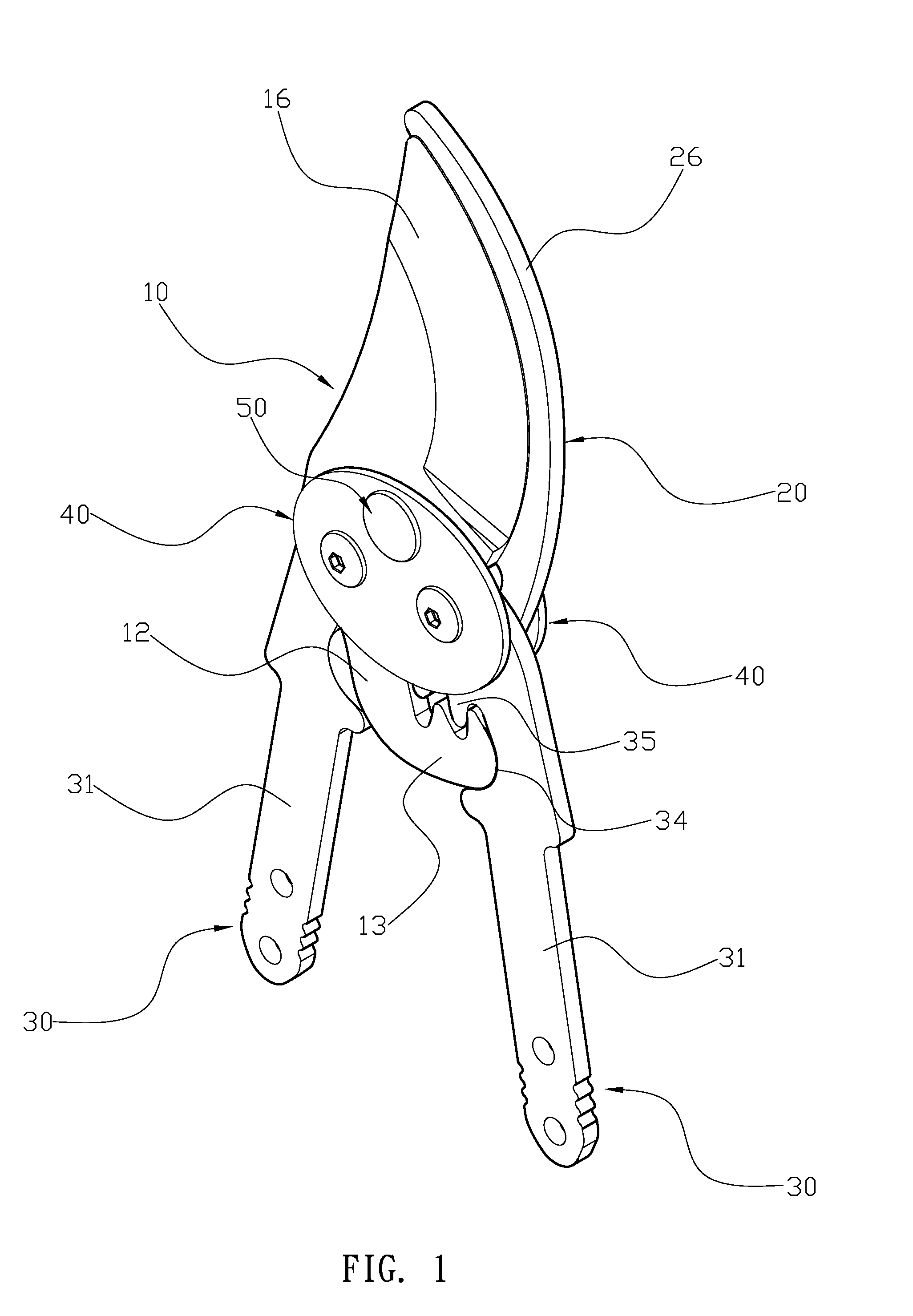
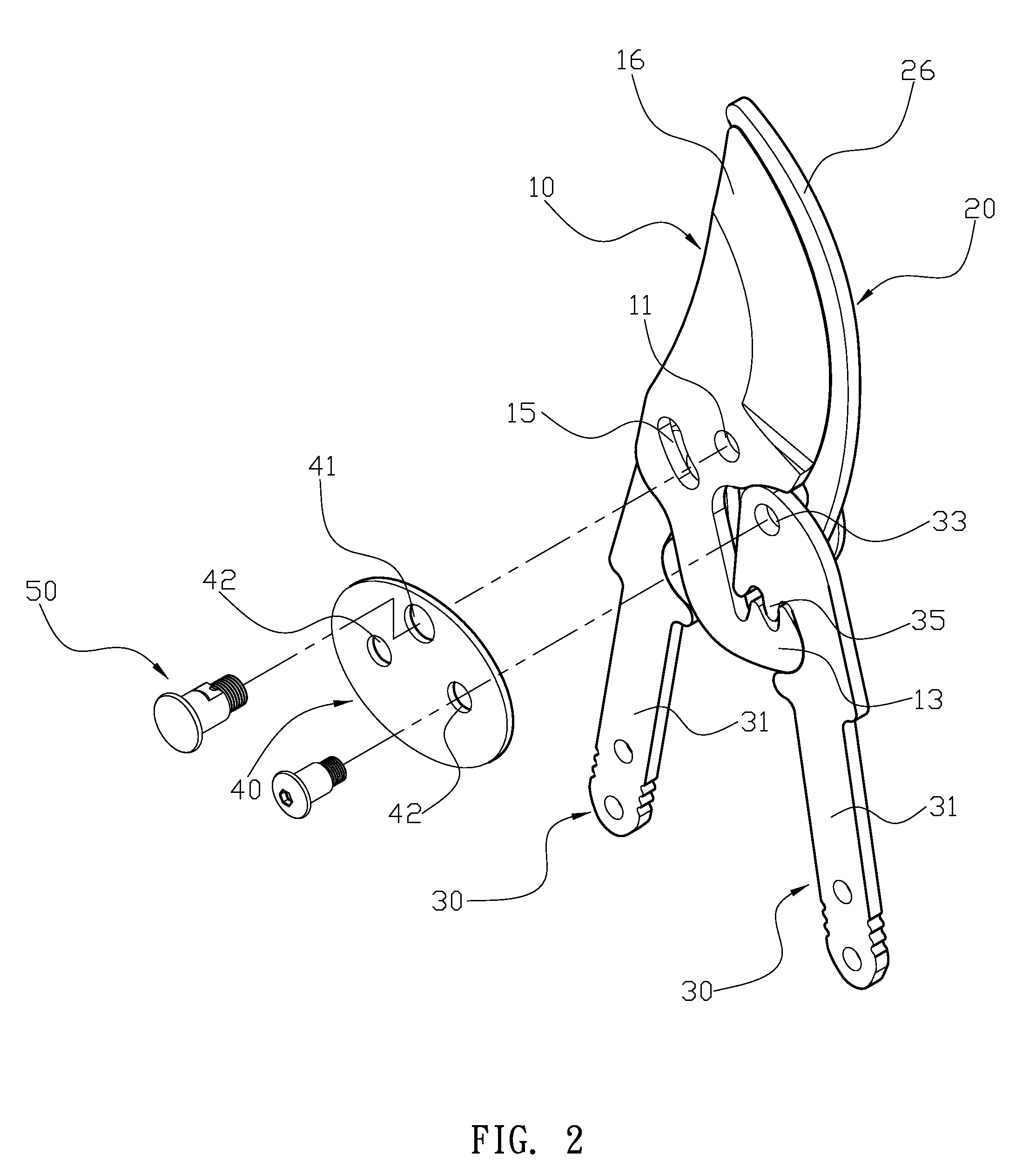
[0022]Please refer to FIG. 1, FIG. 2 and FIG. 3. A shears comprises a main cutting member 10, a minor cutting member 20, two applying arms 30, and the two assembling members 40, all of which are assembled together by at least one nut 51 and screw 50. The main cutting member 10 and the minor cutting member 20 have corresponding shapes and may overlap each other, and the major and minor cutting members both have a first pivot aperture 11, 21 at a middle position and an extended section 12, 22. An end of each extended sections 12, 22 is bent up to form an L-shaped pawl 13, 23 forming a first indentation 14, 24. An arced limiting slot 15, 25 adjacent to each first pivot aperture 11, 21 is respectively formed above the extended section 12, 22, and a tool end 16, 26 is respectively formed at an opposite end of the major and minor cutting members 10, 20. Moreover, the tool ends 16, 26 can be an anvil and a blade or both can be anvils. Each applying arm 30 has a handle 31 at a lower portion...


PUM


Abstract

A garden shears has a main cutting member, a minor cutting member, two applying arms, and two assembling members. The major and minor cutting members both have a first pivot aperture and an extended section. An end of each extended section is bent up to form an L-shaped pawl forming a first indentation; an arced limiting slot is adjacent to each first pivot, and a tool end is respectively formed at an opposite end of the major and minor cutting members. Each applying arm has a handle and an assembling portion, each assembling portion having a second pivot aperture and a second indentation. A top edge of each second indentation has driving teeth that respectively engage with the L-shaped pawls of the major and minor cutting members. Each assembling member has a third pivot aperture and two fourth pivot apertures corresponding to the first pivot apertures and the second pivot apertures.

Description

BACKGROUND OF THE INVENTION[0001]1. Field of the Invention[0002]The present invention relates to garden shears, and more particularly to a garden shears that is capable of limiting a maximum opening range and that requires less operational strength.[0003]2. Description of the Related Art[0004]More and more people enjoy having plants in their living environment; therefore, garden tools are becoming increasingly popular. Garden shears are used for trimming plants. Please refer to FIG. 8. A prior art garden shears has a metal lever 60, a first member 70 and a second member 80. The metal lever 60 has a first pivot joint 61, a blade 62 and an arm 63 having a second pivot joint 64. The second pivot joint 64 and the first pivot joint 61 are separated from each other by a predetermined distance. The first member 70 is pivoted onto the first pivot joint 61 and connected to the metal bar lever. The first member 70 further has an extended jaw 71 coupled with the blade 62 and is able to cut an ...

Claims


Application Information

Patent Timeline
Patent Type & Authority Applications(United States)
IPC IPC(8): B26B13/00
CPCB26B13/26A01G3/021A01G3/0251
Inventor HUANG, YAO-CHUNG
Owner HO CHENG GARDEN TOOLS
Learn More