Thermoelectric energy storage system having two thermal baths and method for storing thermoelectric energy

Active Publication Date: 2012-03-15
ABB (SCHWEIZ) AG
View PDF6 Cites 62 Cited by
  • Summary
  • Abstract
  • Description
  • Claims
  • Application Information

AI Technical Summary

Benefits of technology

[0013]There is a need to provide an efficient thermoelectric energy storage having a high round-trip efficiency, while minimising the system costs involved.
[0014]An exemplary thermoelectric energy storage system having a charging cycle for providing thermal energy to a thermal storage, and a discharging cycle for generating electricity by retrieving the thermal energy from the thermal storage is disclosed. The thermoelectric energy storage system including a working fluid circuit for circulating a working fluid through a first heat exchanger and a second heat exchanger; a thermal stor

Problems solved by technology

All electric energy storage technologies inherently have a limited round-trip efficiency.
The rest of the electrical energy is lost.
The roundtrip efficiency of the TEES system is limited for various reasons rooted in the second law of thermodynamics.
Secondly, the conversion of heat to mechanical work in a heat engine is limited by the Carnot efficiency.
Thirdly, any heat f

Method used


Image

  • Thermoelectric energy storage system having two thermal baths and method for storing thermoelectric energy
  • Thermoelectric energy storage system having two thermal baths and method for storing thermoelectric energy
  • Thermoelectric energy storage system having two thermal baths and method for storing thermoelectric energy

Examples


Embodiment Construction

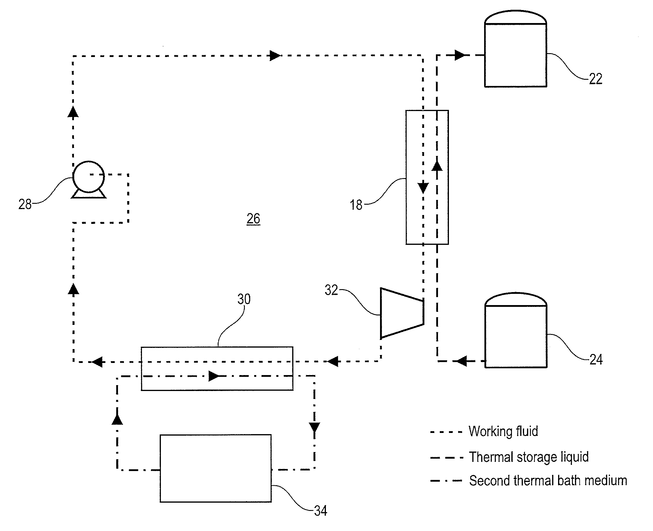
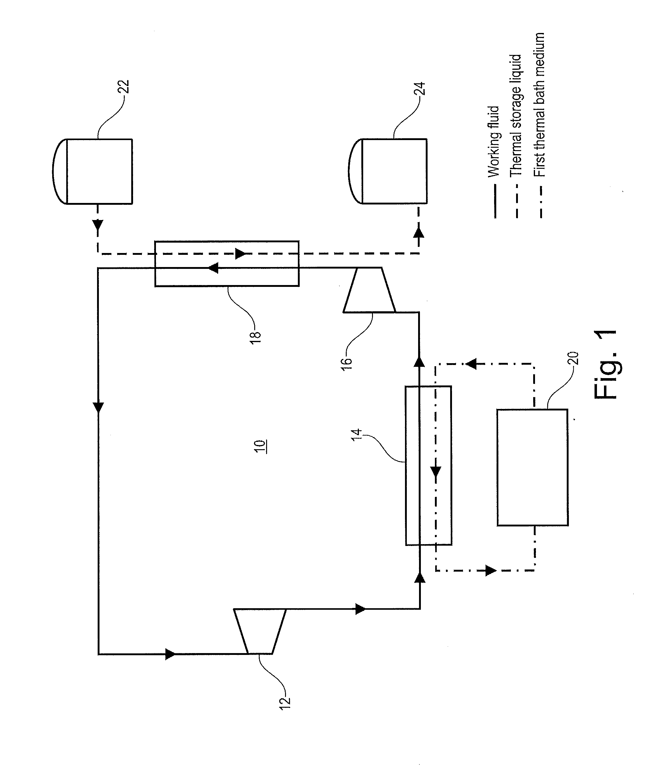
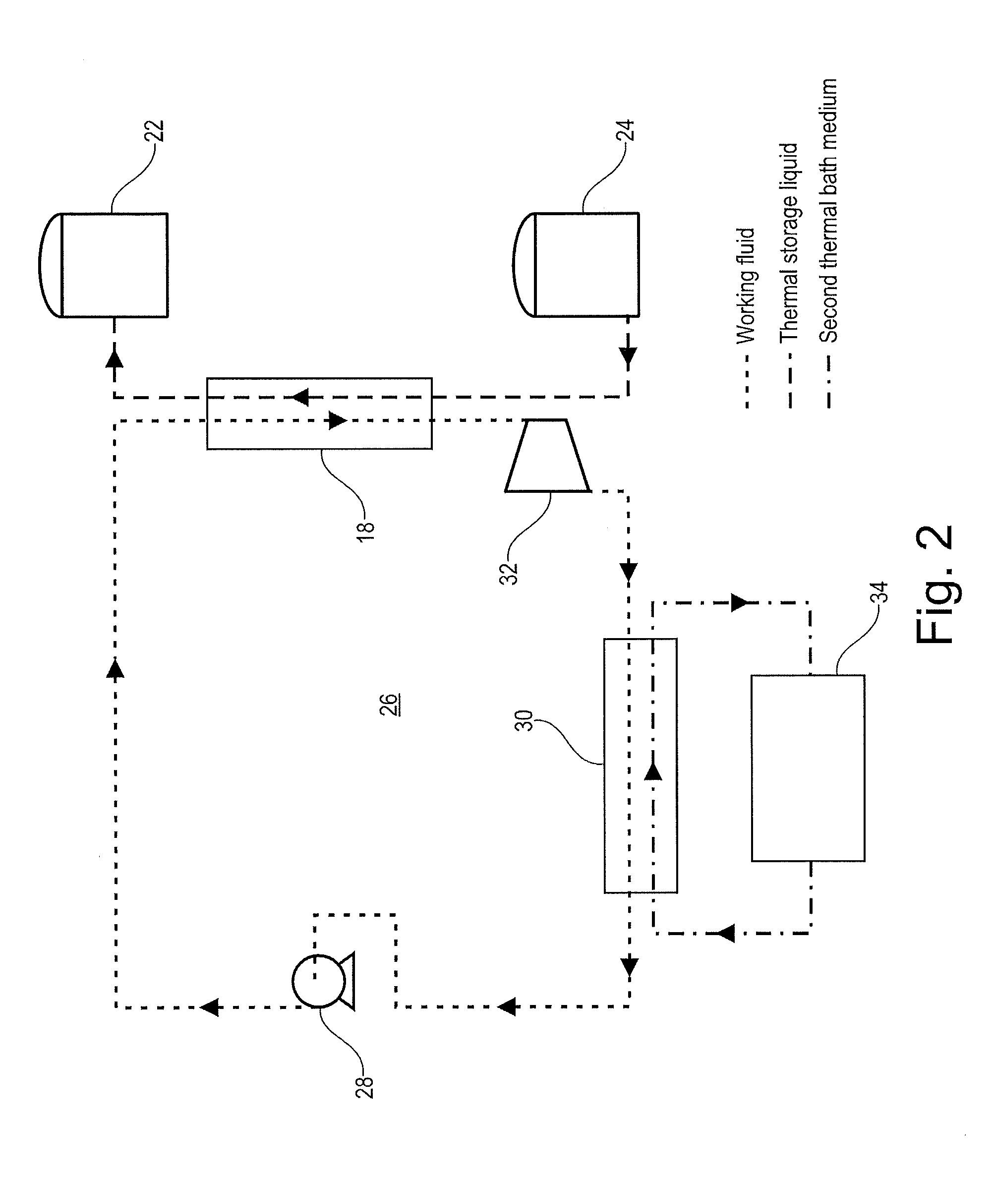
[0025]Exemplary embodiments of the present disclosure provide a thermoelectric energy storage system for converting electrical energy into thermal energy to be stored and converted back to electrical energy with an improved round-trip efficiency.

[0026]An exemplary thermoelectric energy storage system of the present disclosure includes a charging cycle for providing thermal energy to a thermal storage, and a discharging cycle for generating electricity by retrieving the thermal energy from the thermal storage. The thermoelectric energy storage system includes a working fluid circuit for circulating a working fluid through a first heat exchanger and a second heat exchanger, and a thermal storage medium circuit for circulating a thermal storage medium. The thermal storage medium circuit has at least one hot storage tank coupled to a cold storage tank via the first heat exchanger. During a charging cycle, the second heat exchanger is in connection with a first thermal bath, and the temp...


PUM


Abstract

An exemplary system and method for storing and retrieving energy in a thermoelectric energy storage system is disclosed. The thermoelectric energy storage system includes a working fluid that is circulated through a first and second heat exchanger, and a thermal storage medium that is circulated through the first heat exchanger. The second heat exchanger is in connection with a first thermal bath during a charging cycle and with a second thermal bath during a discharging cycle. In this way roundtrip efficiency is improved through minimizing the temperature difference between the first thermal bath and the hot storage tank during charging, and maximizing the temperature difference between the second thermal bath and the hot storage tank during discharging.

Description

RELATED APPLICATIONS[0001]This application claims priority as a continuation application under 35 U.S.C. §120 to PCT / EP2010 / 052732, which was filed as an International Application on Mar. 4, 2010 designating the U.S., and which claims priority to European Application 09157835.1 filed in Europe on Apr. 14, 2009. The entire contents of these applications are hereby incorporated by reference in their entireties.FIELD[0002]The present disclosure relates generally to the storage of electric energy, such as a system and method for storing electric energy in the form of thermal energy in thermal energy storage.BACKGROUND INFORMATION[0003]Known load generators such as nuclear power plants and generators with stochastic, intermittent energy sources such as wind turbines and solar panels, generate excess electrical power during times of low power demand. Large-scale electrical energy storage systems are a means of diverting this excess energy to times of peak demand and balance the overall el...

Claims


Application Information

Patent Timeline
IPC IPC(8): F01K3/00F25B21/04H01L35/30
CPCF02C1/10F02C6/14F02C6/18F03D9/006F28D20/00F03G7/04F05B2220/604Y02E10/72F05D2220/64F03D9/02F03D9/22F03D9/18F03D9/25Y02E60/14Y02E70/30
Inventor HEMRLE, JAROSLAVKAUFMANN, LILIANMERCANGOEZ, MEHMET
Owner ABB (SCHWEIZ) AG
Why Eureka
Try Eureka