Control pedal assembly

a technology of control pedals and components, applied in mechanical control devices, instruments, foot actuation initiations, etc., can solve problems such as difficult insufficiency in insufficiency of foreign matter in accelerators

Active Publication Date: 2012-03-15
HONDA MOTOR CO LTD
View PDF5 Cites 13 Cited by
  • Summary
  • Abstract
  • Description
  • Claims
  • Application Information

AI Technical Summary

Benefits of technology

[0010]According to one aspect of the present invention, a control pedal assembly includes a pedal bracket, a control pedal, an urging device and a communicating portion. The pedal bracket is secured to a vehicle body and has a housing space. The control pedal is swingably supported by a support shaft disposed in the housing ...

Problems solved by technology

Such a control pedal assembly can make ingress of foreign matter into an accelerator side difficu...

Method used


Image

  • Control pedal assembly
  • Control pedal assembly
  • Control pedal assembly

Examples


embodiment 1

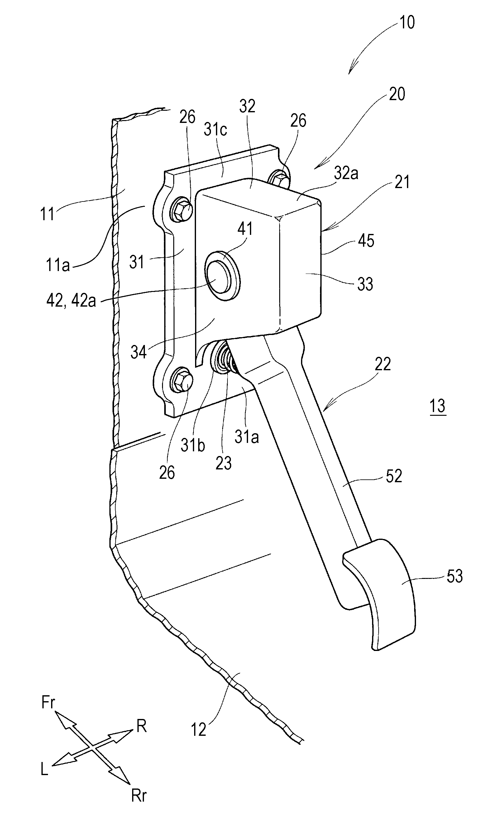
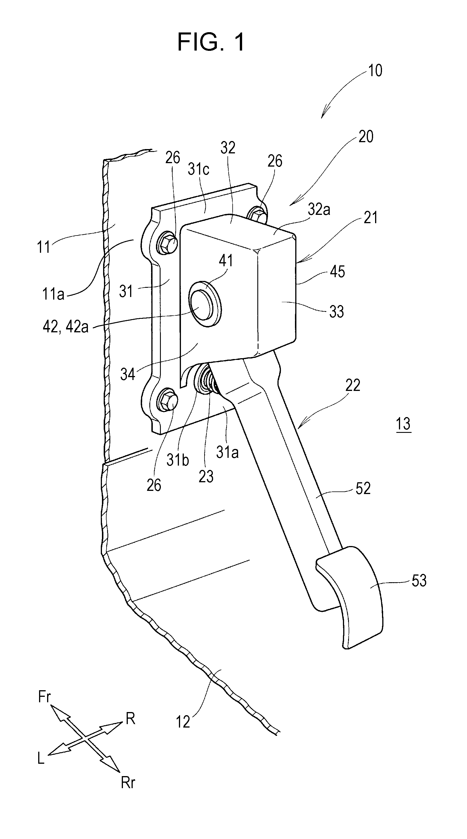
[0025]A control pedal assembly 20 according to Embodiment 1 is described below.

[0026]As shown in FIGS. 1 and 2, the control pedal assembly 20 is provided on a dashboard lower-section 11 of a vehicle body 10 so as to be disposed close to the feet of a driver in a passenger compartment 13.

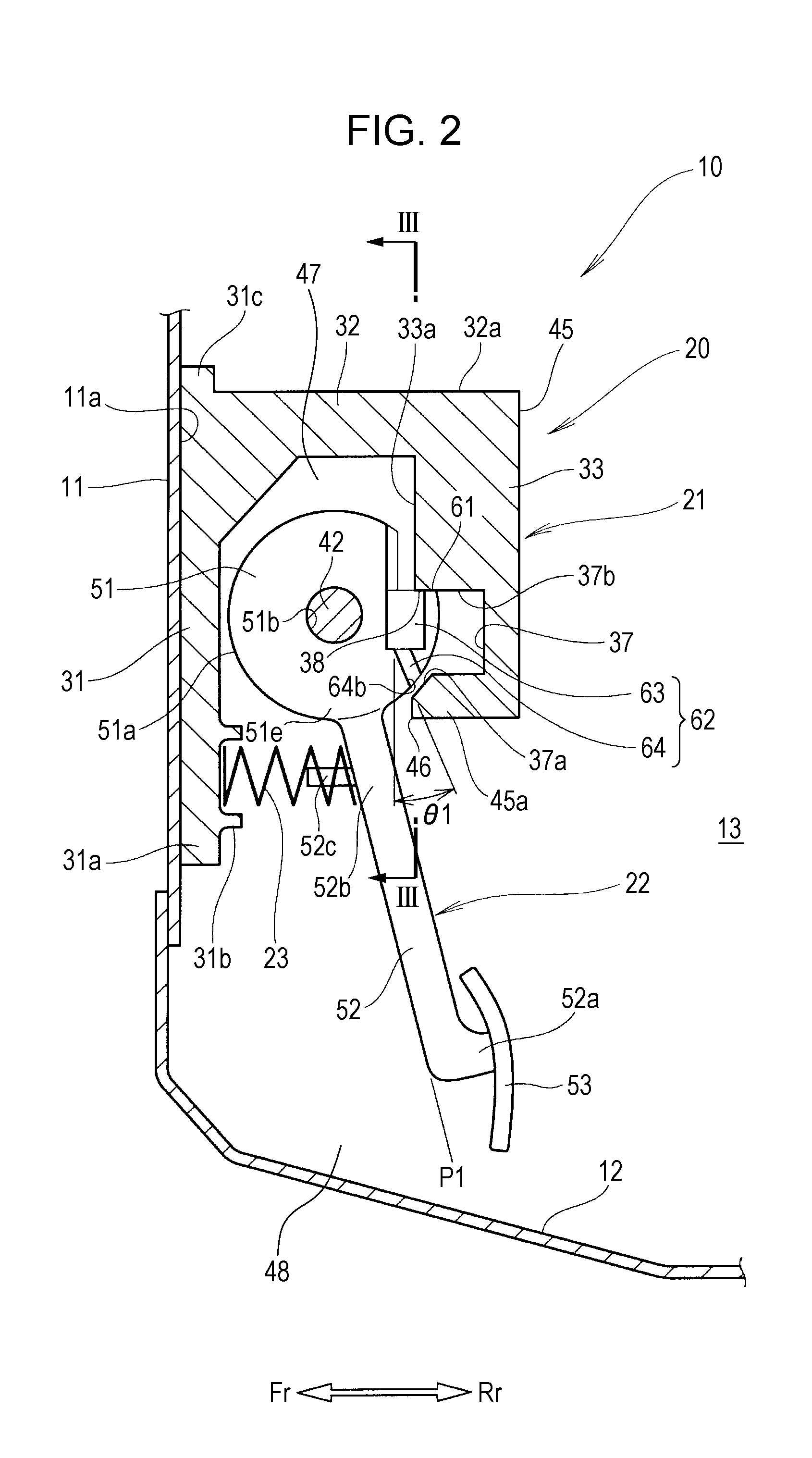
[0027]The control pedal assembly 20 has a pedal bracket 21 secured to the vehicle body 10, an accelerator pedal (control pedal) 22 that is swingably supported by the pedal bracket 21, and a compression spring (urging device) 23 that urges the accelerator pedal 22 toward the rear of the vehicle body.

[0028]The pedal bracket 21 is secured to the vehicle body 10 (more specifically, a surface 11a of the dashboard lower-section 11) with a bolt 26 so as to be disposed in the passenger compartment 13.

[0029]The pedal bracket 21 has a mounting plate 31, a upper wall 32, a rear wall 33, and side walls 34, 35 (see FIG. 3 for the right side wall 35).

[0030]The mounting plate 31 is secured to the surface 11a of the...

embodiment 2

[0104]As shown in FIG. 8, the control pedal assembly 80 has the same structure as the control pedal assembly 20 according to Embodiment 1, except that an accelerator pedal 81 is provided instead of the accelerator pedal 22 according to Embodiment 1.

[0105]The accelerator pedal 81 is formed of a resin material and has a base 82 supported by a support shaft 42, an arm 83 extending downward toward the rear of the vehicle body from the base 82, and a pedal 53 provided at a lower end 83a of the arm 83.

[0106]The accelerator pedal 81 shown as an example is formed of a resin material, but may be formed of other materials such as steel and cast iron.

[0107]As shown in FIGS. 9 and 10, the base 82 has a circumferential portion 82a formed in a substantially circular shape as seen from the side and a supporting hole 82b penetrating therethrough in the middle thereof. The support shaft 42 is inserted through the supporting hole 82b.

[0108]The base 82 is provided at a left side (side of the pedal) 8...


PUM


Abstract

A control pedal assembly includes a pedal bracket, a control pedal, an urging device and a communicating portion. The pedal bracket is secured to a vehicle body and has a housing space. The control pedal is swingably supported by a support shaft disposed in the housing space of the pedal bracket. The urging device is to urge the control pedal toward a rear of a vehicle body. The communicating portion is provided at a rear of the support shaft relative to the vehicle body between the control pedal and the pedal bracket to connect a space above the control pedal and a space below the control pedal.

Description

CROSS-REFERENCE TO RELATED APPLICATIONS[0001]The present application claims priority under 35 U.S.C. §119 to Japanese Patent Application No. 2010-207304, filed Sep. 15, 2010, entitled “Control Pedal Assembly”. The contents of this application are incorporated herein by reference in their entirety.BACKGROUND OF THE INVENTION[0002]1. Field of the Invention[0003]The present invention relates to a control pedal assembly.[0004]2. Discussion of the Background[0005]A vehicle control pedal assembly having an accelerator pedal that is swingably supported by a support shaft in a mounting base thereof, the mounting base having a surface (surface facing the pedal) facing the accelerator pedal formed in a convex shape and the accelerator pedal having a surface (surface facing the base) facing the mounting base formed in a convex shape, is known (for example, see Japanese Unexamined Patent Application Publication No. 2007-191009).[0006]The vehicle control pedal assembly described above can use th...

Claims


Application Information

Patent Timeline
IPC IPC(8): G05G1/44
CPCB60T7/06Y10T74/20888G05G1/44Y10T74/20528
Inventor YAMAGUCHI, AYUMUMANDO, KIYOHIROIMAMURA, KENSOMATSUDA, AKIO
Owner HONDA MOTOR CO LTD
Why Eureka
Try Eureka