Display switching device

a switching device and display technology, applied in the field of display switching apparatuses, can solve the problems of increasing the processing time increasing the processing complexity of images, and increasing the cost of information processing terminals, so as to reduce the total processing time of rendering, delay the display of frame images, and reduce the effect of skipped frames

Inactive Publication Date: 2012-03-15
PANASONIC INTELLECTUAL PROPERTY CORP OF AMERICA
View PDF4 Cites 14 Cited by
  • Summary
  • Abstract
  • Description
  • Claims
  • Application Information

AI Technical Summary

Benefits of technology

[0008]With the above structure, the total processing time for rendering by the first and the second rendering component is shortened after switching buffers. Therefore, the disp

Problems solved by technology

Since image processing is continually becoming more complicated, in addition to a universal buffer, information processing terminals are provided with a more expensive high-speed buffer capable of f

Method used


Image

  • Display switching device
  • Display switching device
  • Display switching device

Examples


embodiment 1

1. Embodiment 1

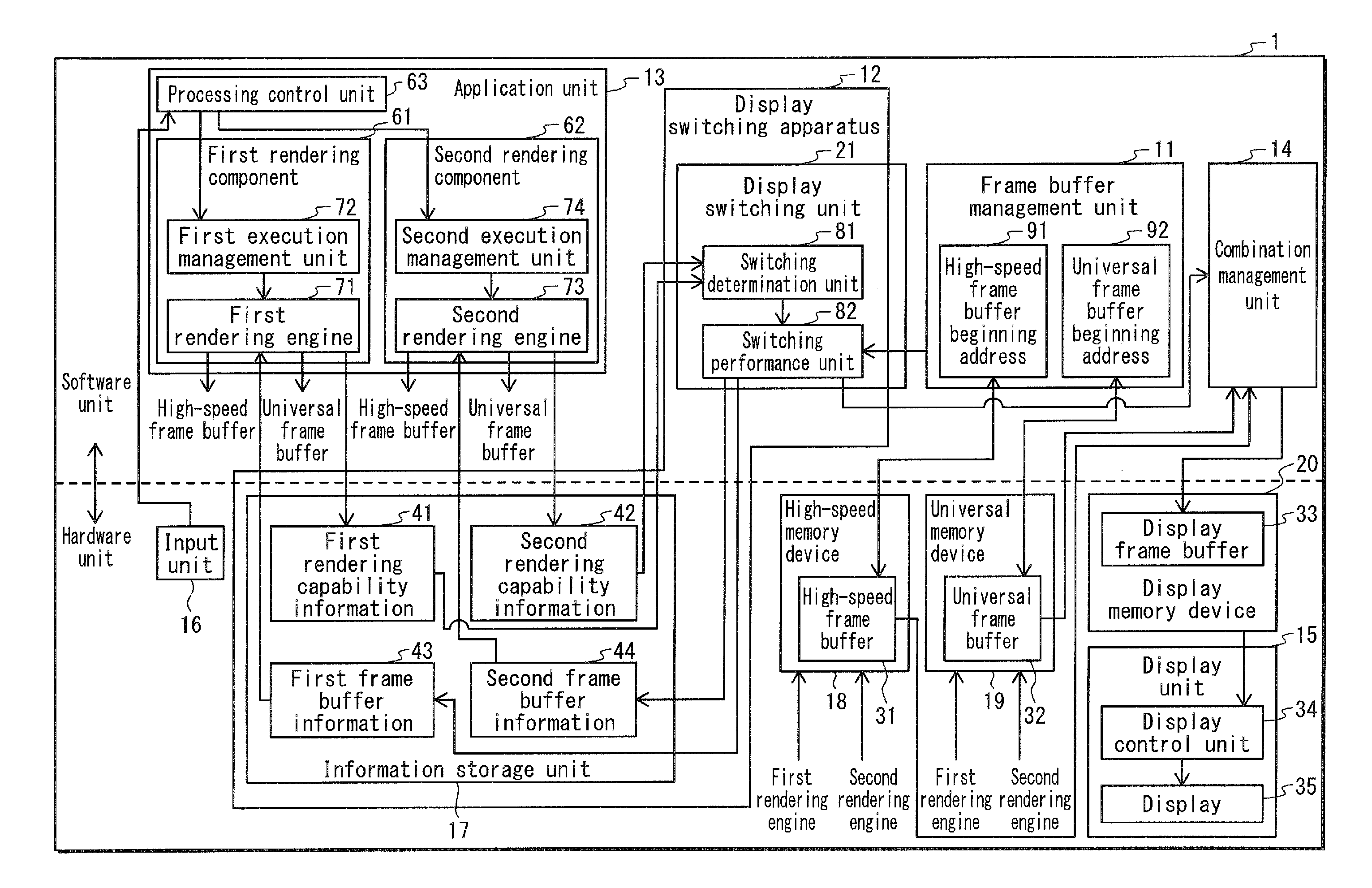
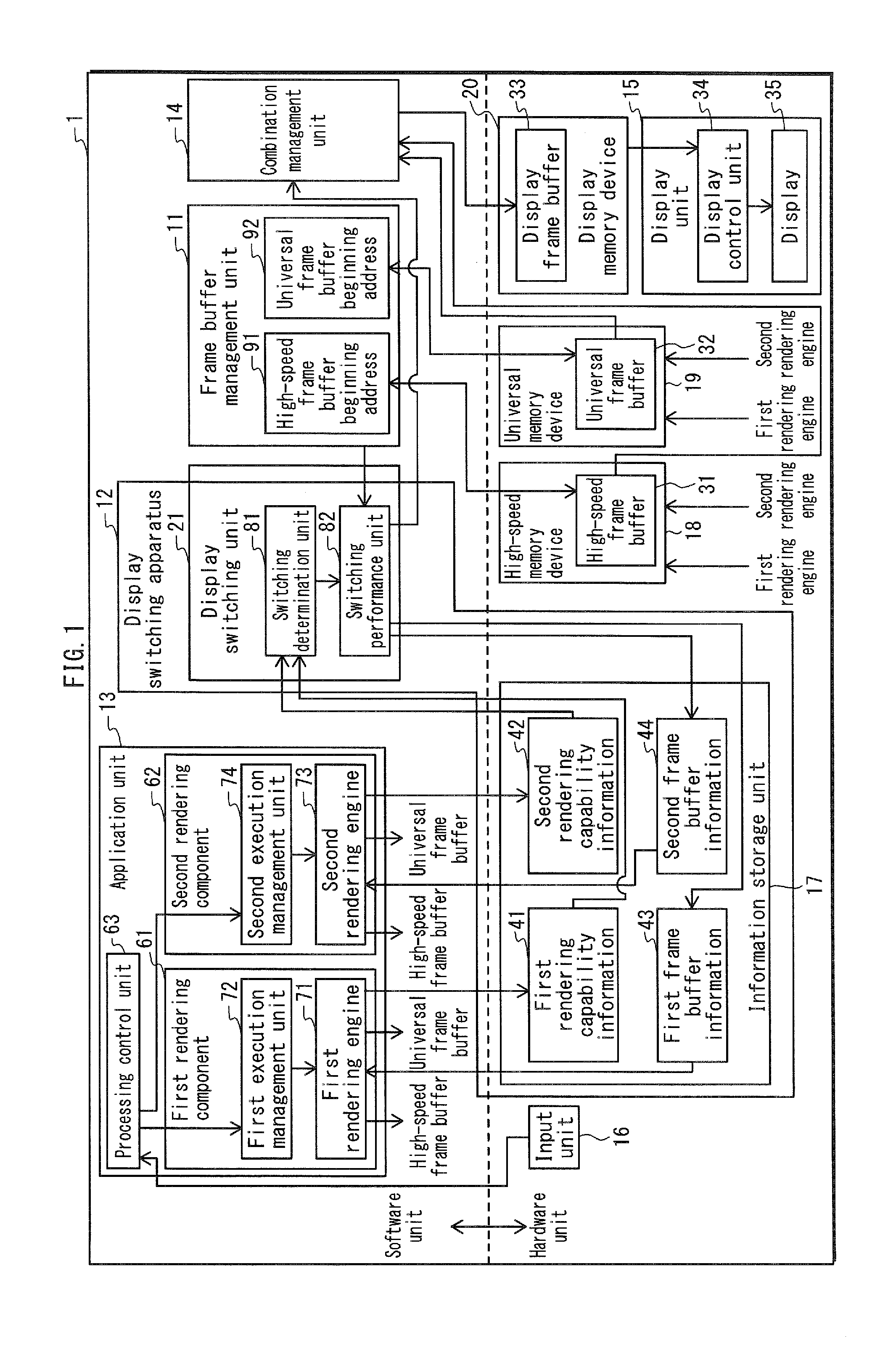
[0037]An information processing terminal 1 provided with a display switching apparatus according to an embodiment of the present invention is a portable information processing terminal provided with a touchscreen display. By way of example, the information processing terminal 1 executes a navigation application that displays the current position of the information processing terminal 1 on a map. This application includes a component that is responsible for the function of displaying the map (hereinafter referred to as a “first rendering component”) and a component that is responsible for the function of displaying a photograph (hereinafter referred to as a “second rendering component”). The map is displayed with images generated by other rendering components superimposed thereon as necessary, such as a photograph of actual scenery at a certain spot on the map.

[0038]Normally, each time the user holding the information processing terminal 1 moves, the current position o...

embodiment 2

2. Embodiment 2

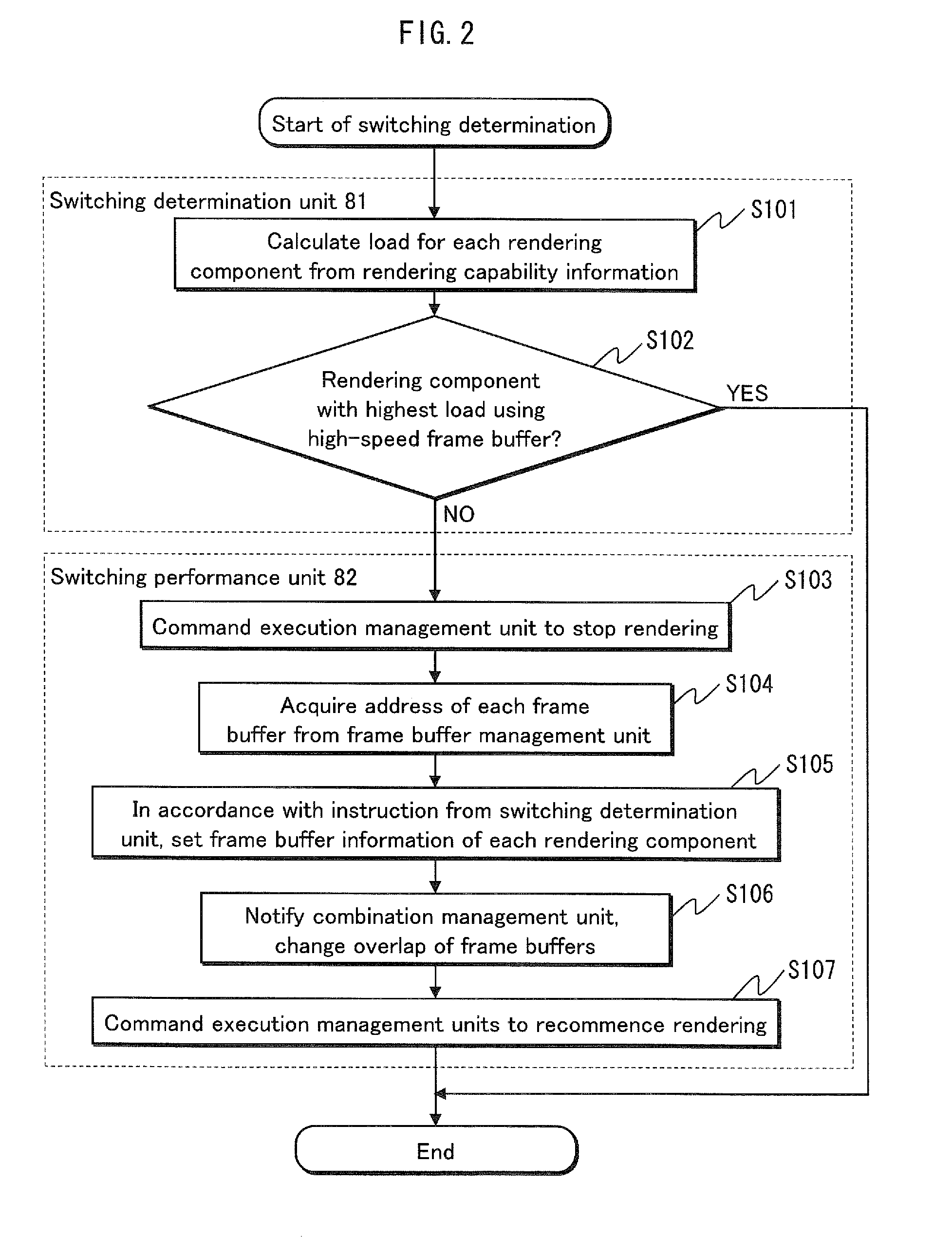
[0091]In Embodiment 1, the determination of whether to switch the buffers is made in accordance with the CPU load. In Embodiment 2, when it is determined that buffer switching in necessary, the most appropriate of a plurality of pre-established buffer switching procedures is furthermore selected. Buffers are switched according to the selected buffer switching procedure. The most appropriate buffer switching procedure is selected by predicting rendering delay, dropped frames, and CPU load for each switching procedure. A comprehensive determination is then made based on the predictions.

[0092]The plurality of buffer switching procedures refers to the following three procedures. (1) Switching the buffers without copying the contents thereof back and forth (hereinafter, “first switching procedure”). (2) Copying the content of the buffer used by the first rendering component 61 into the buffer used by the second rendering component 62 and then switching buffers (hereinafter...


PUM


Abstract

Provided is a display switching apparatus that reduces delayed display, and the like, of frame images. An information processing terminal 1 is provided with a first rendering component 61 that, in each first time interval, generates and writes an image to a buffer, a second rendering component 62 that, in each second time interval, generates and writes an image to a buffer, a frame buffer management unit 11 that allocates a high-speed frame buffer 31 on a high-speed memory device 18 and a universal frame buffer 32 on a universal memory device 19, and a display switching apparatus 12 that includes a switching determination unit 81 that repeatedly calculates a rendering load for each rendering component and a switching performance unit 82 that switches the buffers allocated to the rendering components when the high-speed frame buffer 31 is not allocated to the rendering component with the higher rendering load.

Description

TECHNICAL FIELD[0001]The present invention relates to display switching apparatuses in information processing terminals that display a plurality of superimposed images, and in particular to controlling switching between a plurality of buffers storing images.BACKGROUND ART[0002]In recent years, it is increasingly common for information processing terminals to show a plurality of superimposed images on a display. Such information processing terminals include car navigation systems, cellular telephones, and the like. For example, a car navigation system might display a map, along with a photographic image taken at a certain spot on the map superimposed thereon. Since image processing is continually becoming more complicated, in addition to a universal buffer, information processing terminals are provided with a more expensive high-speed buffer capable of faster processing than a universal buffer. The high-speed buffer is assigned to certain processes in order to shorten processing time...

Claims


Application Information

Patent Timeline
IPC IPC(8): G06F15/00
CPCG06T1/60G09G2360/08G09G5/399G09G5/393
Inventor KASHIMOTO, KAZUTOSHI
Owner PANASONIC INTELLECTUAL PROPERTY CORP OF AMERICA
Why Eureka
Try Eureka