Appliance with luminous housing in environment-dependent color

Inactive Publication Date: 2012-03-15
KONINKLIJKE PHILIPS ELECTRONICS NV
View PDF7 Cites 10 Cited by
  • Summary
  • Abstract
  • Description
  • Claims
  • Application Information

AI Technical Summary

Benefits of technology

[0011]In one embodiment of the appliance, the exterior surface of the optically transmissive part of the housing covers at least 25%, and preferably more than 50% of the total exterior surface of the appliance that is visible to a an observer when the appliance is used in accordance with its intended purpose. In relation to a (robotic) vacuum cleaner, for example, this means that the part of its exterior surface that during vacuuming faces the ground being vacuumed may be left out from the calculation. The minimum figures for the portion of the optically transmissive part in the overall visible housing area helps to ensure that the housing part whose color can be adapted is of significance to the perceived color of the appliance.
[0012]In an advantageous embodiment of the appliance according to the invention, the optically transmissive part of the housing is formed by an optical wave guide. The nature of an optical wave guide enables light coupled into it to be distributed easily around the housing of the appliance, for example to promote substantially homogenous coloring thereof. The wave guide may typically be characterized as a ‘leaking’ wave guide, i.e. a wave guide for visible light that is configu

Problems solved by technology

However, since it is infeasible to produce an appliance in all the colors of the rainbow, some consumers may still be disappointed with the necessarily limited choice in colors.
As each room may have its own color scheme, the robotic vacuum cleaner may fit in perfectly with one room, but appear dreadful against the backdrop of another.
Apart from causing a less than satisfying aesthetic appreciation, the color m

Method used


Image

  • Appliance with luminous housing in environment-dependent color
  • Appliance with luminous housing in environment-dependent color

Examples


Embodiment Construction

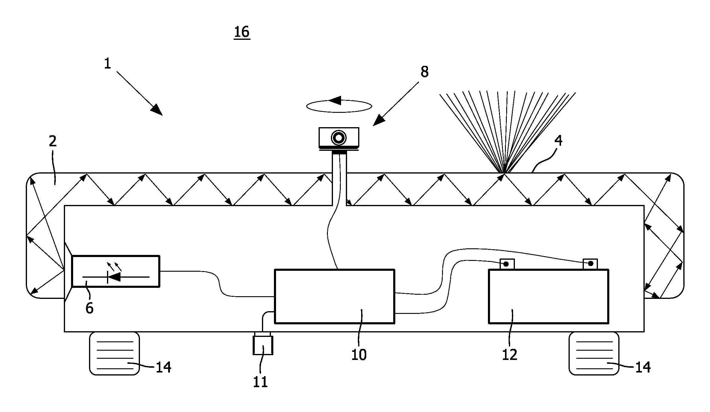
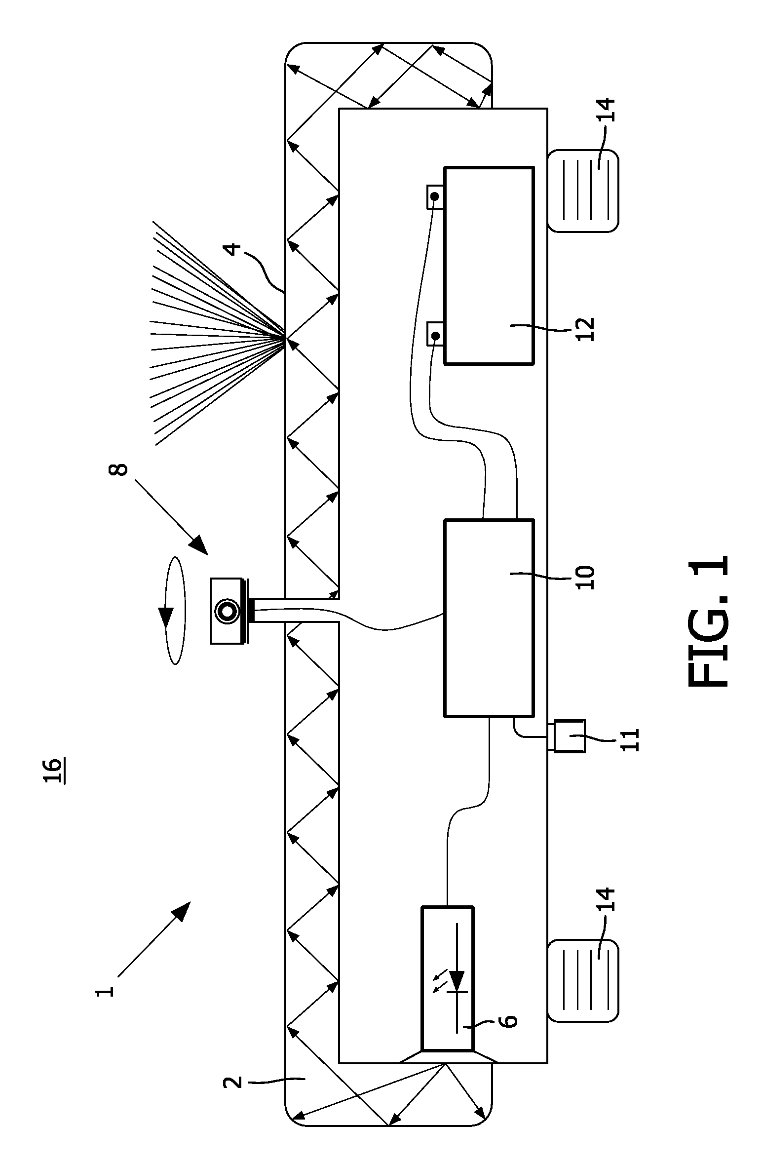
[0028]An appliance 1 according to the present invention may comprise a housing that includes an optically transmissive part 2, a controllable light source assembly 6, a color vision system 8 and a control unit 10. These separately identifiable yet collaborating components of the appliance 1 will hereafter be discussed and exemplified in turn, first in abstracto and subsequently with reference to the exemplary robotic vacuum cleaner 1 shown in FIG. 1. For convenience, reference numerals relating to FIG. 1 are also included in the general, abstract discussion of the invention.

[0029]The housing, i.e. the outer accommodating structure of an appliance 1, includes an optically transmissive part 2, for example in the form of an electromagnetic wave guide that is capable of guiding visible light. Optical wave guides in themselves are known in the art and exist in different forms, such as dielectric wave guides and hollow structures having a highly reflective inner surface. The latter are so...


PUM


Abstract

Appliance comprising a housing, wherein a part of said housing is optically transmissive, said optically transmissive part having an exterior surface through which light travelling through the optically transparent part is transmitted, so as to cause the transmitted light to be visible upon viewing the exterior surface. The appliance further comprises a controllable light source assembly, capable of producing light in a variety of colors, and configured to couple produced light into the optically transmissive part of the housing. The appliance also includes a control unit, and a color vision system, configured to optically observe an environment of the appliance, and to output data relating to colors of the observed environment to the control unit. The control unit is configured to control a housing color to be produced by the light source assembly, whereby said housing color is determined in dependence of the data received from the color vision system.

Description

FIELD OF THE INVENTION[0001]The present invention pertains to appliances, in particular domestic appliances, having a customizable appearance.BACKGROUND[0002]Domestic appliances typically include a housing in one or more dominant colors. The preponderant color of a (robotic) vacuum cleaner, for example, may be red. But no matter what predominant color a manufacturer chooses for its appliance, it is likely that there will be a demand for differently colored specimens as well. This is simply because color is a highly subjectively appreciated quality. To meet such demand, a manufacturer may choose to fabricate its appliances in a range of colors. The otherwise same vacuum cleaner may for example be marketed in red, green and blue. This approach enables a consumer to pick the vacuum cleaner of his choice, such as the one best fitting his home interior. However, since it is infeasible to produce an appliance in all the colors of the rainbow, some consumers may still be disappointed with ...

Claims


Application Information

Patent Timeline
IPC IPC(8): H04N7/18
CPCA47L9/00A47L9/2805A47L9/2857A47L9/2873H05B33/0803A47L9/30A47L2201/00G05D25/02A47L9/2894H05B45/20H05B45/00H05B45/30
Inventor FLINSENBERG, INGRID CHRISTINA MARIAMEERBEEK, BERENT WILLEMSAERBECK, MARTINHOLENDERSKI, LESZEK
Owner KONINKLIJKE PHILIPS ELECTRONICS NV
Why Eureka
Try Eureka