Instrument for eye examination

a technology for eye examination and instruments, which is applied in the field of eye examination instruments, can solve the problem of limiting the possibility of determining their location to a discrete number, and achieve the effects of reducing the number of eye examinations

a technology for eye examination and instruments, which is applied in the field of eye examination instruments, can solve the problem of limiting the possibility of determining their location to a discrete number, and achieve the effects of reducing the number of eye examinations

US20120062842A1Active Publication Date: 2012-03-15CENTVUE

Image

  • Instrument for eye examination
  • Instrument for eye examination
  • Instrument for eye examination

Examples


Embodiment Construction

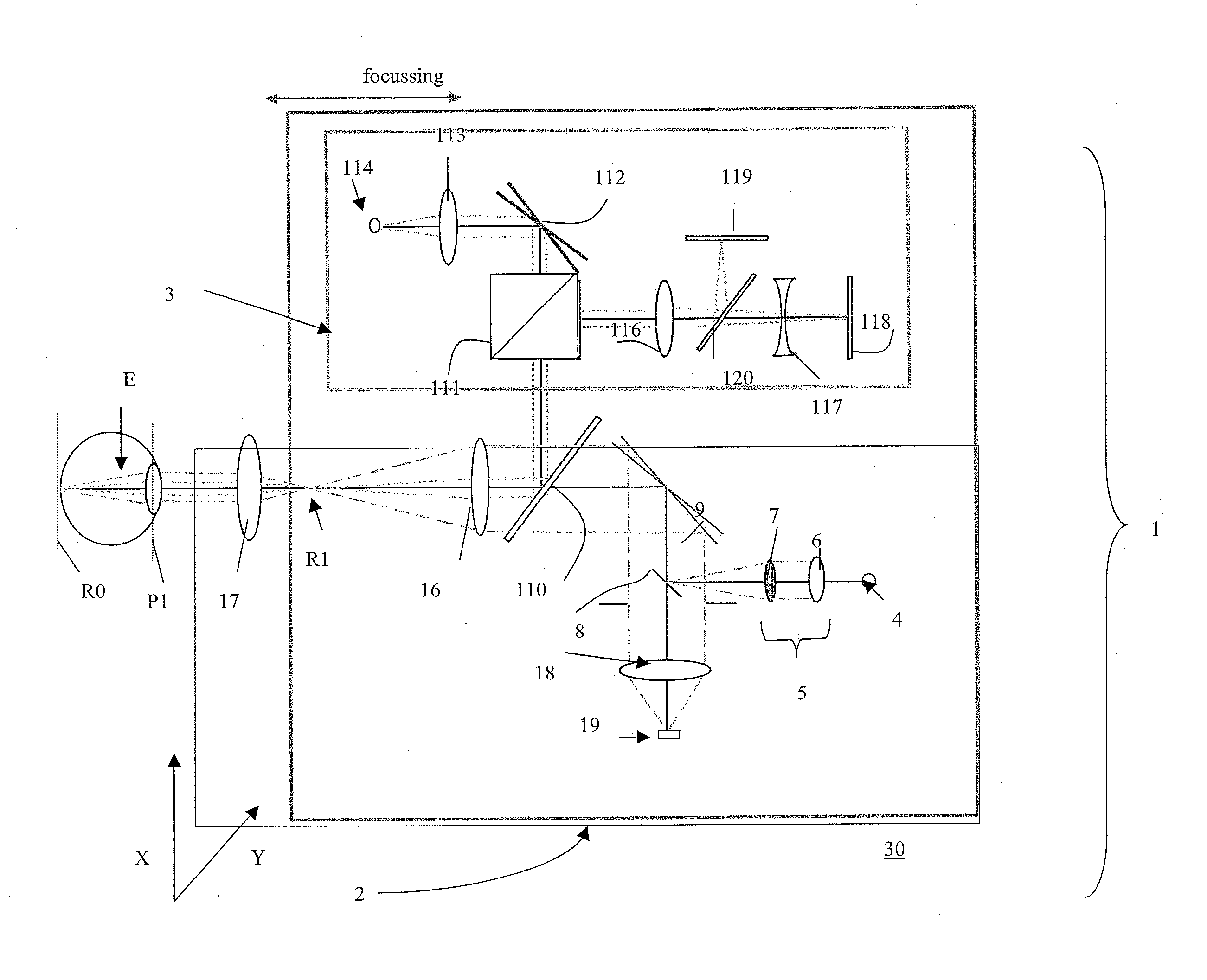
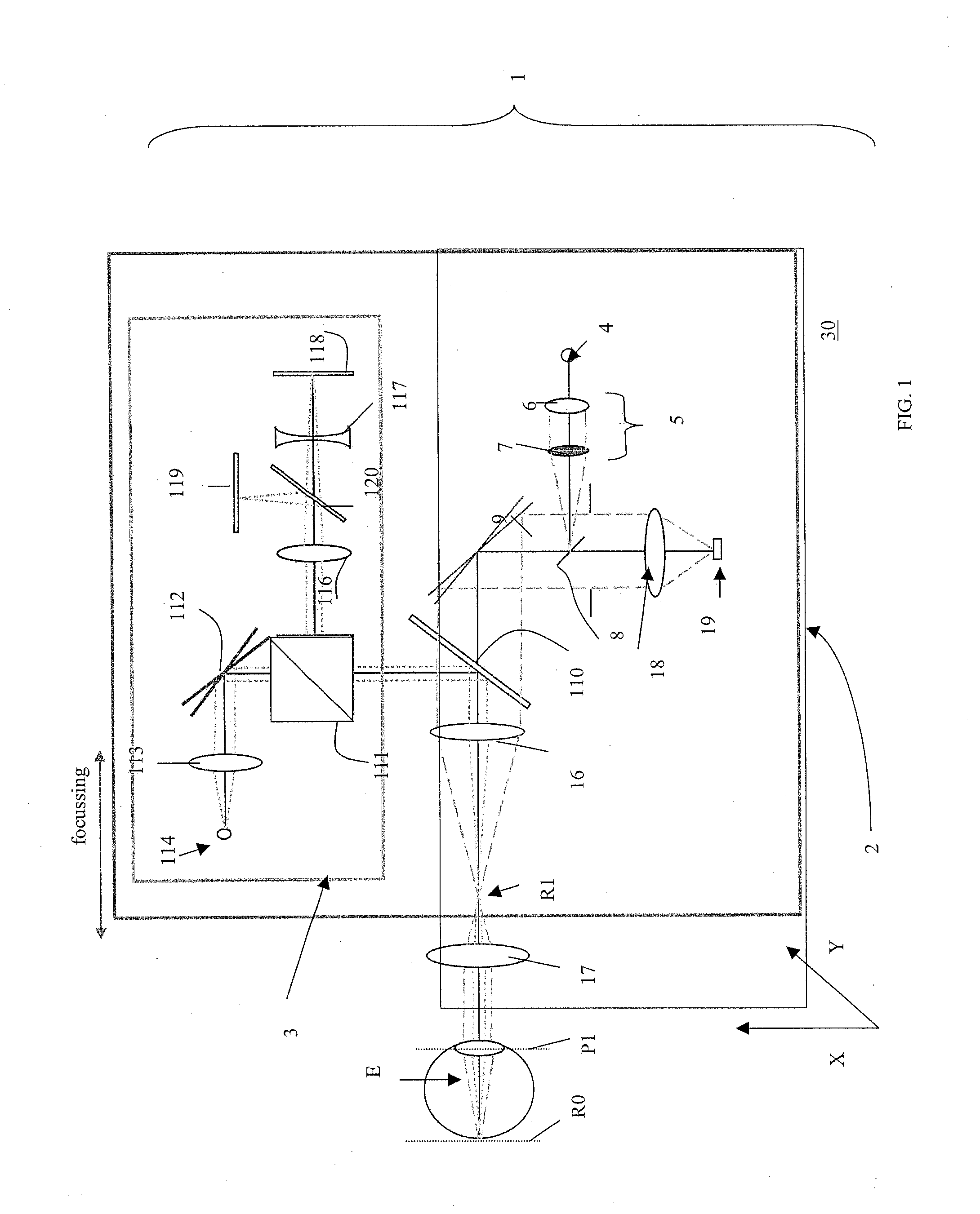
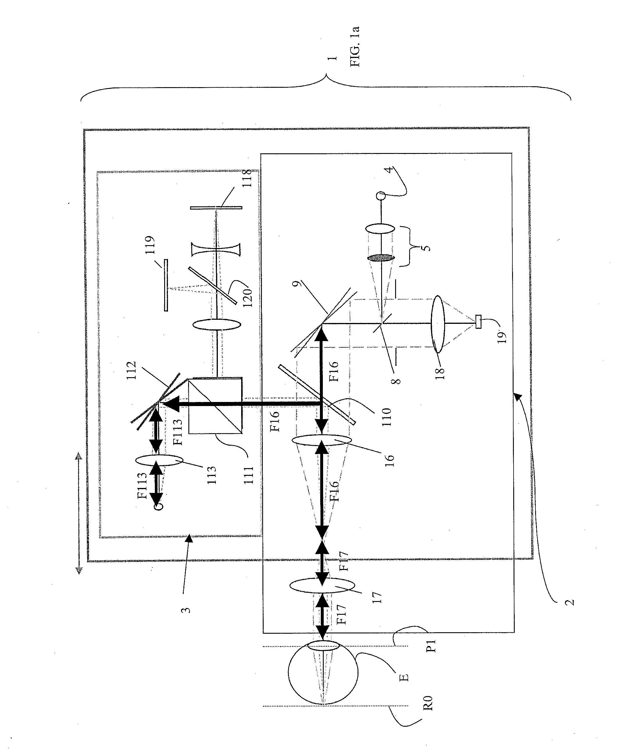
[0039]With reference to FIG. 1, 1 indicates an optical head of an instrument for eye examination according to the present invention. The instrument including the optical head 1 is used to examine an eye E of a patient, eye which is depicted only very schematically in FIG. 1.

[0040]The instrument further includes a control board 40 (shown in FIG. 6) and a software (see FIG. 7) executed in an appropriate computer 50, for the control of the optical head 1, as better outlined below. The software and the computer are also responsible of the communication with an operator of the instrument, via preferably a monitor or display 51 on which information relative to the performed test on the patient's eye or to the instrument status are shown.

[0041]The optical head 1 includes an imaging system 2 and a projection system 3, both controlled by the control board 40, computer 50 and software.

[0042]The imaging system 2, preferably a laser scanning imaging system, even more preferably a line laser sca...


PUM


Abstract

The present invention relates to an instrument for eye (E) examination, the system including an imaging system (2) to produce images of a portion of the eye to be examined; a projection system (3) to project a stimulus of visible light on a location in the portion of the eye to be examined and a background light on the portion of the eye to be examined; in which the projection system (3) has a telecentric design to uniformly project the stimulus and the background and includes a light source (114) and a movable mirror (112) which is moved according to the location of stimulus projection.

Description

TECHNICAL FIELD[0001]The present invention relates to an instrument for eye examination, and in particular, but not exclusively, for retina examination, of the type including the characteristics specified in the preamble to main claim 1.TECHNOLOGICAL BACKGROUND[0002]In the examination of the human eyes, in particular of the retinas of the same, fundus imaging is an essential tool. For this purpose, Scanning Laser Ophthalmoscopes (SLO) have been recently developed in order to rapidly obtain high resolution images of the ocular fundus and its internal structures.[0003]Among the possible tests that a SLO may perform, the assessment of the function of the macular area of the human retina, in order to detect presence of any macular degeneration, preferably in its early stages, is an extremely important one, in order to obtain an indication on whether the macular function is normal, suspect or abnormal.[0004]Generally, the assessment above described is obtained acquiring both images of th...

Claims


Application Information

Patent Timeline
15 Mar 2012
Publication
US20120062842A1
IPC
A61B3/12; A61B3/10
CPC
A61B3/1025; A61B3/0091
Inventors
GRIGGIO, PAOLA; TURRA, FABIO