Optical waveguide splitters

Active Publication Date: 2012-03-15
LUMENTUM TECH UK LTD
View PDF3 Cites 13 Cited by
  • Summary
  • Abstract
  • Description
  • Claims
  • Application Information

AI Technical Summary

Benefits of technology

[0029]The interferometer may be provided with an arm photodetector section within each interferometer arm adjacent the optical recombiner, the interferometer having first and second interferometer output waveguides with an output photodetector section being provided within each interferometer output waveguide adjacent the optical recombiner, the optical recombiner being the controllable optical splitter, the method further comprising measuring an effective split ratio (SRe) of the intensities of the light within the arm photodetector sectio

Problems solved by technology

With appropriate choice of the phase modulation, constructive and destructive optical interference between the components will take place on recombination, resulting in an amplitude modulated combined signal.
The optical splitting performance of such MMI couplers devices is limited by the fabrication accuracy of the MMI region.
Further the optical splitting is susceptible to thermally induced and stress induced performance variations.
Further, the optical performance of MMIs and integrated optical circuits into which MMIs are incorporated can drift during operational life, due to variations in ambient conditions and the effects of ageing.
This current spreading reduces the current density closest to the re-imaging node, compensating for which requires an increased total current injection, leadin

Method used


Image

  • Optical waveguide splitters
  • Optical waveguide splitters
  • Optical waveguide splitters

Examples


Embodiment Construction

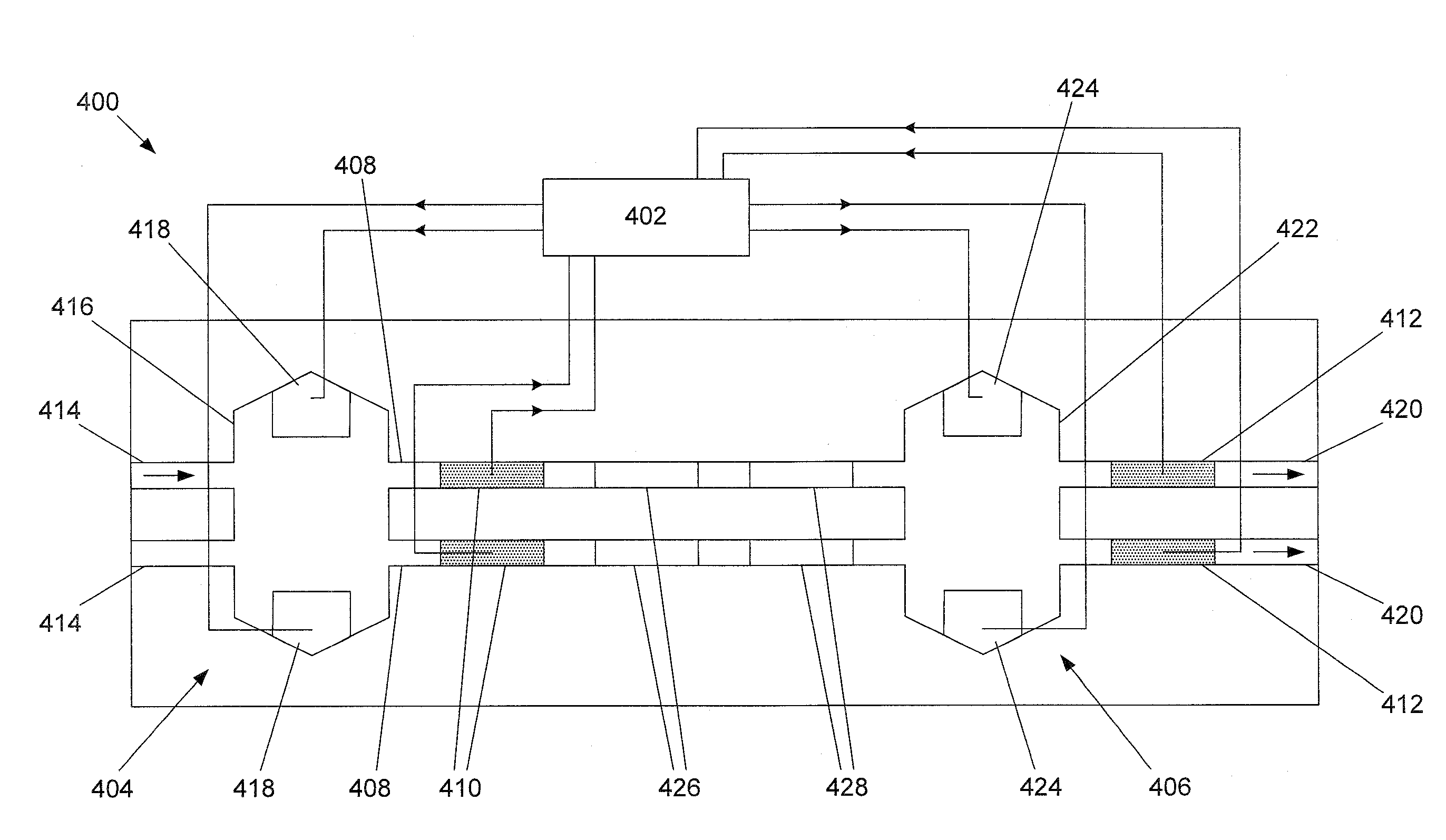
[0039]FIG. 1 schematically illustrates a tunable multimode interference (MMI) coupler 100 according to the present invention. The tunable MMI coupler 100 is formed as part of a ridge waveguide structure formed on the front surface of a substrate 102. The tunable MMI coupler 100 has an MMI region 104, waveguides 106A to 106D and tuning electrodes 108.

[0040]The waveguides 106A to 106D are substantially monomode and optically couple with the MMI region 104.

[0041]The tuning electrodes 108 are provided on the surface of the MMI region 102. On the opposite side of the substrate 102 from the tuning electrodes 108, the back surface is provided with a back electrode 110.

[0042]The MMI region 104 is barrel-shaped, having sides that taper outward from each end 112A and 112B to a waist 114 halfway along the length of the region. The MMI region 104 has an electrically insulating region 116 abutting the region of the MMI region 104 covered by the tuning electrodes 108.

[0043]In use, substantially m...


PUM


Abstract

An Mach-Zehnder interferometer (500) incorporates a tunable multimode interference coupler comprising a tunable MMI coupler (504) with a tuning electrode (524) on a surface of a tunable MMI region (516) and an electrically-insulating region provided within the tunable MMI region. The MMI region is tuned in response to detection of a photocurrent measured by integrated photodetector section (510, 512). Such a tunable MZO is particularly advantageous in enabling a controlled split tio of an optical splitter.

Description

FIELD OF THE INVENTION[0001]The present invention concerns optical waveguide splitters comprising multimode interference couplers and in particular monolithically integrated optical circuits comprising such optical waveguide splitters and control schemes for optical waveguide splitters.BACKGROUND OF THE INVENTION[0002]In the field of optical telecommunications components, monolithically integrated optical circuits are widely used. Such optical circuits commonly comprise a plurality of optical waveguides (e.g. ridge waveguides) connected by means of optical splitters, at which light is split or recombined to or from different branch waveguides. Examples of such optical circuits are Mach-Zehnder interferometer (MZI) devices, such as Mach-Zehnder modulators (MZMs). MZMs are used to modulate an optical signal with an electrical data signal by splitting the optical signal into two components, phase modulating one component relative to the other, and recombining the components. With appro...

Claims


Application Information

Patent Timeline
IPC IPC(8): G01B9/02
CPCG02B6/2813G02B2006/12159G02F2201/58G02F2001/217G02F1/225G02F1/217
Inventor LANGLEY, LLOYDGRIFFIN, ROBERTBETTY, IAN BRIAN
Owner LUMENTUM TECH UK LTD
Why Eureka
Try Eureka