Adjustable sructure for lamp stand

a lamp stand and adjustable technology, applied in the field of lamp stands, can solve the problems of difficult to fix positions, and easy slackening of locking parts or pivot positions, and achieve the effect of reducing production costs, simplifying the entire structure, and easy and convenient assembly

Inactive Publication Date: 2012-03-15
CHANG TSUNG CHANG
View PDF2 Cites 19 Cited by
  • Summary
  • Abstract
  • Description
  • Claims
  • Application Information

AI Technical Summary

Benefits of technology

[0008]Hence, the object of the present invention is to provide an adjustable structure for lamp stand, which enables simplification of the entire structure, making for easy and more convenient assembly, and reducing production costs, thereby increasing market competitiveness.
[0009]The first objective of the present invention is to provide an adjustable structure for lamp stand that primarily uses an oil pressure type telescopic link disposed between bar supports to supplement position fixing of the structure, thereby preventing slackening of the structure because of elastic fatigue.
[0010]Another objective of the present invention is to provide the adjustable structure for lamp stand with a configuration comprising three components, including a first bar support, a second bar support and a telescopic link, therewith fabricating an easily adjustable structure enabling fixing position thereof, as well as providing simple and convenient assembly.
[0011]Yet another objective of the present invention is for the adjustable structure for lamp stand to extrude hollow aluminum material to form the first bar support and the second bar support, thereby enabling the structure to be lightweight and have low cost. The pin connected positions are equally fitted with soft sleevings to provide a friction fit, increase abrasion resistant properties, and extend the serviceable life of the entire structure.

Problems solved by technology

However, because the aforementioned lamp stand structure requires that the springs be installed in the interior space of the supporting rods, thus, design of the fixing positions between the supporting rods must be extremely precise, otherwise, they will easily come apart.
Hence, slackening of the locking portions or pivot positions very easily occurs during the process of repeated tightening and loosening adjustment over a long period of time, making it difficult to fix positions thereof.
Moreover, because assembly of such structures is complicated, and cost is high, thus, it is difficult to improve productivity, resulting in a decline in market competitiveness.

Method used


Image

  • Adjustable sructure for lamp stand
  • Adjustable sructure for lamp stand
  • Adjustable sructure for lamp stand

Examples


Embodiment Construction

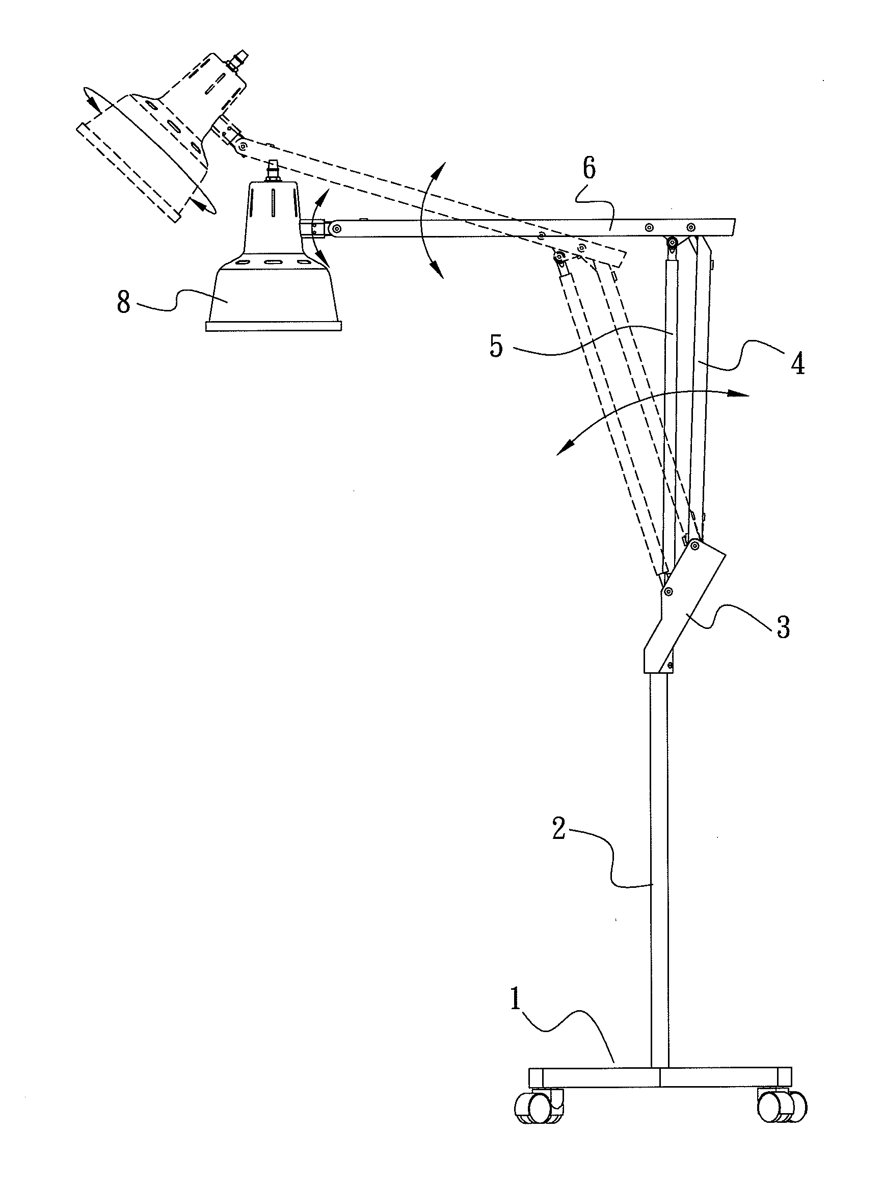
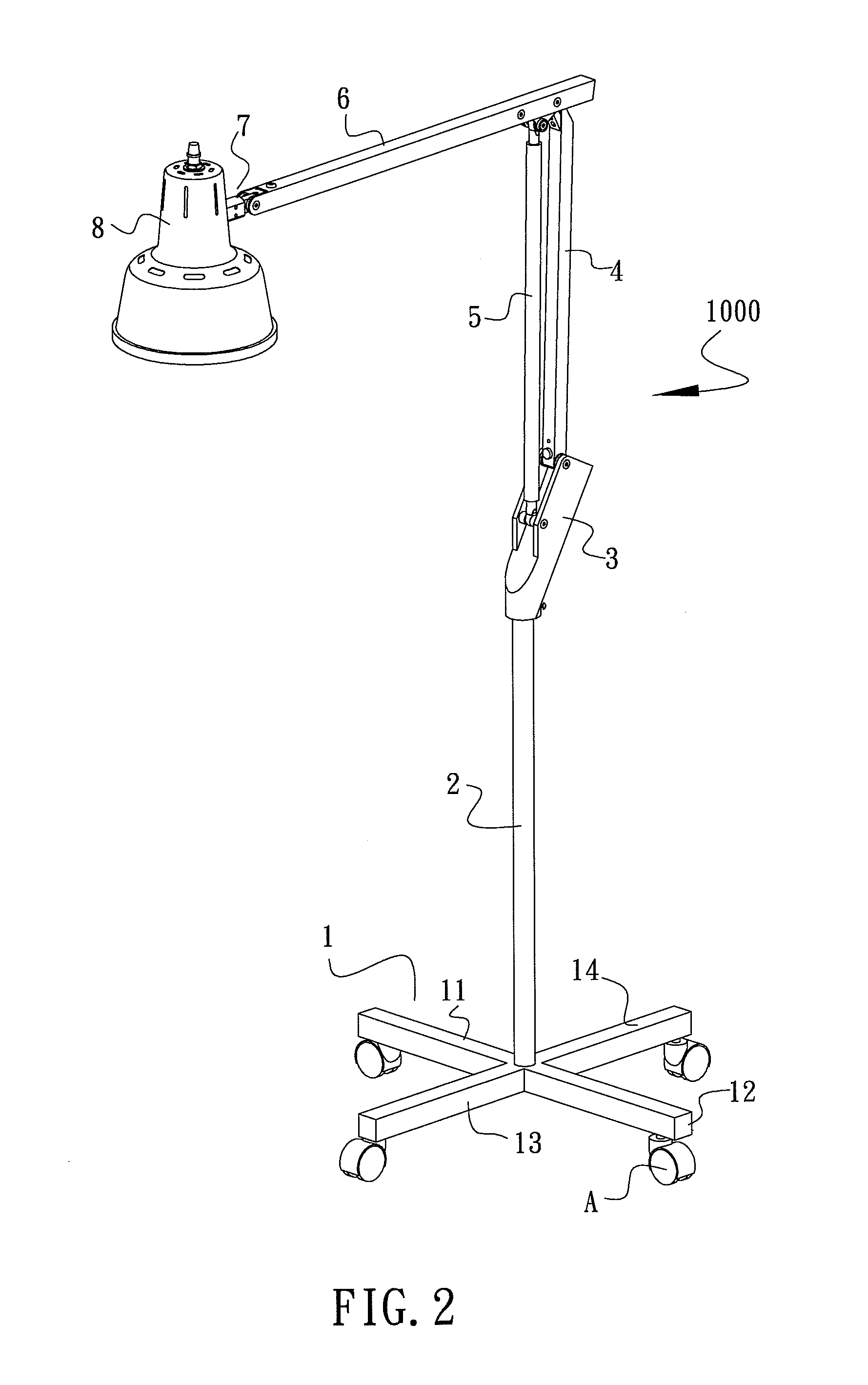
[0018]The adjustable structure for lamp stand of the present invention, as depicted in FIG. 2, consists of a lamp stand 1000 comprising a base 1, a standard bar 2, a swivel mount 3, a first bar support 4, a telescopic link 5, a second bar support 6 and a lamp swivel component 7.

[0019]In which, the base 1 is fitted with four cross bars 11, 12, 13, 14, and a bottom end of each of the cross bars 11, 12, 13, 14 is fitted with a sliding wheel A, thereby enabling sliding movement of the base 1.

[0020]The upper portion of the base 1 is fitted with the vertical standard bar 2, and the swivel mount 3 is disposed on the upper end of the standard bar 2. The swivel mount 3 assumes an inclined disposition, the upper surface of which is provided with two assembling hole mounts, respectively being upper hole mounts 31 and lower hole mounts 32 (see FIG. 3). The upper hole mounts 31 enable the bottom end of the first bar support 4 to be pin connected thereto, and the lower hole mounts 32 enable the b...


PUM


Abstract

An adjustable structure for lamp stand, in which a swivel mount is fitted to the upper portion of a base, thereby enabling ends of a first bar support and a telescopic link to be pin connected to the swivel mount, while the other ends are pin connected to a second bar support. A lamp swivel component is disposed on the end of the second bar support. Accordingly, relative positions between the first bar support, the second bar support and the telescopic link can be freely adjusted, while still providing stable support to the structure.

Description

BACKGROUND OF THE INVENTION[0001](a) Field of the Invention[0002]The present invention relates to a lamp stand, and more particularly to a novel adjustable structure for a lamp providing means for adjusting at will the entire structure, while having a simple configuration, which can be conveniently assembled, and substantially reduces production costs.[0003](b) Description of the Prior Art[0004]Referring to FIG. 1, which shows a lamp stand of the prior art, which has been widely used as a lamp stand by beautician professionals for many years, wherein a lamp stand 100 is primarily assembled from two sets of juxtaposed supporting rods 101, 102 mutually connected. Pivots 103, 104 are respectively disposed at rotation corner areas of the two sets of juxtaposed supporting rods 101, 102, and an end of the second set of supporting rods 102 enables a supplementary apparatus 107, such as a magnifying glass or an illuminating lamp, and the like, to be disposed thereon to enable the beautician...

Claims


Application Information

Patent Timeline
Patent Type & Authority Applications(United States)
IPC IPC(8): F21V21/26
CPCF21V21/26F21S6/006
Inventor CHANG, TSUNG-CHANG
Owner CHANG TSUNG CHANG
Why Eureka
Try Eureka