Pulse field assisted spin momentum transfer MRAM design

a technology of momentum transfer and pulse field, applied in information storage, static storage, digital storage, etc., to achieve the effect of high-stable c-mode switching

Active Publication Date: 2012-03-15
TAIWAN SEMICON MFG CO LTD
View PDF10 Cites 12 Cited by
  • Summary
  • Abstract
  • Description
  • Claims
  • Application Information

AI Technical Summary

Benefits of technology

[0018]This object will be met by patterning the STT-MTJ cells into a horizontal C-shape so that highly stable C-mode switching is engaged and also adding additional word lines to generate

Problems solved by technology

However, this design causes the traditional “half-select” problem, in which some of the cells not intended to be programmed, but beneath the additio

Method used


Image

  • Pulse field assisted spin momentum transfer MRAM design
  • Pulse field assisted spin momentum transfer MRAM design
  • Pulse field assisted spin momentum transfer MRAM design

Examples


first embodiment

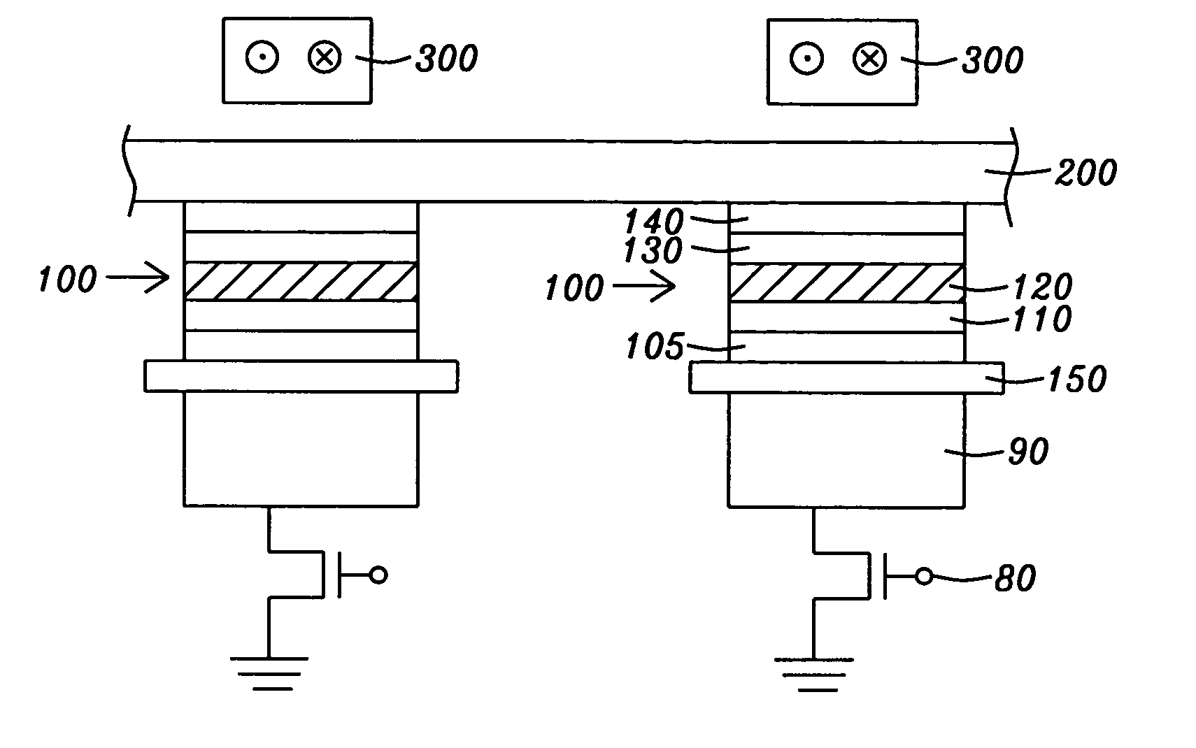
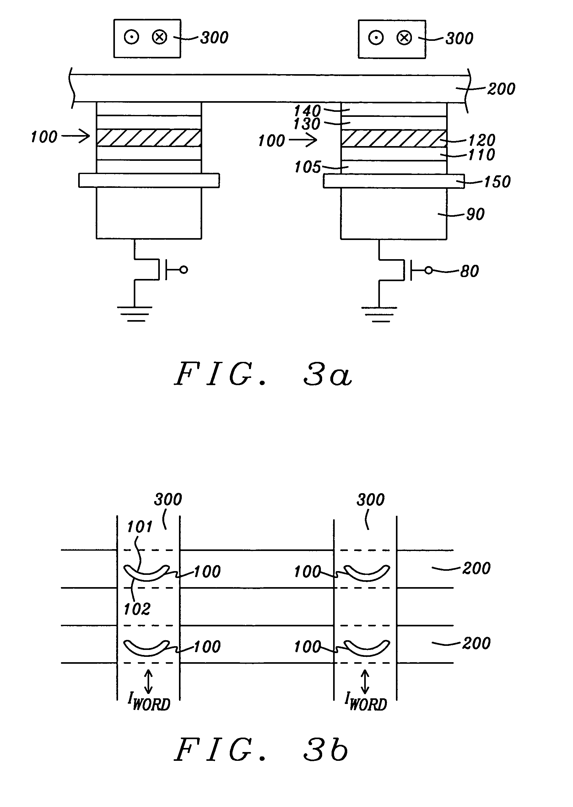
[0030]Referring to schematic FIG. 3a, there is shown an MRAM configuration corresponding to the present invention. The figure shows a vertical cross-sectional view of four adjacent, identical MTJ cells formed in a STT configuration and operating in accord with the STT mode of operation. Only two cells (100) can be seen because of the perspective. Each of two facing cells is positioned beneath a common current carrying line (200), the bit line. Vertically separated and insulated from the bit line and the MTJ cells, there are two word lines (300) that are directed transversely to the plane of the figure and shown in vertical cross-section. Current in the word lines can flow in either direction as shown by the circled dots (out of plane) and circled crosses (into plane), but always so as to assist the magnetization switching, as will be shown below.

[0031]Going vertically downward in either cell, there is first shown a capping layer (140) contacting the bit line and protecting the cell,...

second embodiment

[0034]Referring now to schematic FIG. 4a, there is shown an MRAM configuration corresponding to the present invention. The figure shows a vertical cross-sectional view of four adjacent, identical MTJ cells (100) formed in a STT configuration and operating in accord with the STT mode of operation. Only two cells can be seen because of the perspective. Each of two facing cells is positioned beneath a common current carrying line (200), the bit line. Vertically separated from the bit line, and directly above it, there is shown a word line (300) that is directed parallel to the bit line. The perspective of the figure shows only one bit line and one word line, although an identical arrangement, or a multiplicity of such arrangements, as that shown could be positioned behind or in front of the illustration.

[0035]Going vertically downward in either cell, there is first shown a capping layer (140) contacting the bit line and protecting the cell, beneath the capping layer there is shown a ma...


PUM


Abstract

An MRAM array structure and a method of its operation that is not subject to accidental writing on half-selected elements. Each element of the MRAM is an MTJ (magnetic tunneling junction) cell operating in accord with an STT (spin torque transfer) scheme for changing its free layer magnetization state and each cell is patterned to have a C-shape in the horizontal plane. The cell thereby operates by C-mode switching to provide stability against accidental writing by half-selection. During operation, switching of a cell's magnetization is accomplished with the assist of the pulsed magnetic fields of additional word lines that are formed either orthogonal to or parallel to the existing bit lines and that can carry currents in either direction as required to provide the assist.

Description

BACKGROUND OF THE INVENTION[0001]1. Field of the Invention[0002]This invention relates generally to a spin torque transfer (STT) magnetic random access memory (STT-MRAM) cell formed in a magnetic tunneling junction (MTJ) configuration and patterned in a C-shape. In particular, it relates to the use of an additional word line to provide a pulsed magnetic field that assists in switching the magnetization of such a cell.[0003]2. Description of the Related Art[0004]The conventional magnetic tunneling junction (MTJ) device is a form of ultra-high magnetoresistive (MR) device in which the relative orientation of the magnetic moments of parallel, vertically separated magnetized layers, controls the flow of spin-polarized electrons tunneling through a very thin dielectric layer (the tunneling barrier layer) formed between those layers.[0005]Referring to FIG. 1 there is shown a highly schematic illustration of a prior art MTJ cell that, for the purposes of the following descriptions, can be ...

Claims


Application Information

Patent Timeline
IPC IPC(8): G11C11/00
CPCG11C11/1675G11C11/161G11C11/1659
Inventor MIN, TAICHEN, QIANGWANG, PO KANG
Owner TAIWAN SEMICON MFG CO LTD
Why Eureka
Try Eureka