
Temperature sensor and temperature sensor system

a temperature sensor and temperature sensor technology, applied in the field of temperature sensors, can solve the problems of insufficient reliability of a temperature sensor obtained, inability to check the existence of bubbles, and insufficient filling density of vibration-resistant filler in the metallic protective tube, so as to prevent the migration of high-temperature and ensure the detection of temperature accuracy of the temperature sensor

Inactive Publication Date: 2012-03-15
SHIBAURA ELECTRONICS CO LTD
View PDF13 Cites 30 Cited by
  • Summary
  • Abstract
  • Description
  • Claims
  • Application Information

AI Technical Summary

Benefits of technology

[0024]According to the temperature sensor of the present invention, it becomes possible to prevent the high-temperature migration caused by the adherence of a conductive substance to the area between lead wires and to keep the sealed condition of a temperature sensing element by a covering material. Therefore, it is possible to stably ensure the detected temperature accuracy of the temperature sensor.

Problems solved by technology

Although due to the volatilization of a binder during the hardening of the vibration-resistant filler bubbles may remain after hardening, it is impossible to check the existence of bubbles.
Furthermore, because the vibration-resistant filler during the insertion into the metallic protective tube is in a powdery state, the filling density of the vibration-resistant filler in the metallic protective tube is not sufficient.
Therefore, it cannot be said that a temperature sensor which is obtained has sufficient reliability against variations in oxygen partial pressure, and the accuracy of detected temperatures is unstable.

Method used


Image

  • Temperature sensor and temperature sensor system
  • Temperature sensor and temperature sensor system
  • Temperature sensor and temperature sensor system

Examples


first embodiment

[0037]Hereinafter the present invention will be described in detail on the basis of the embodiments shown in the accompanying drawings.

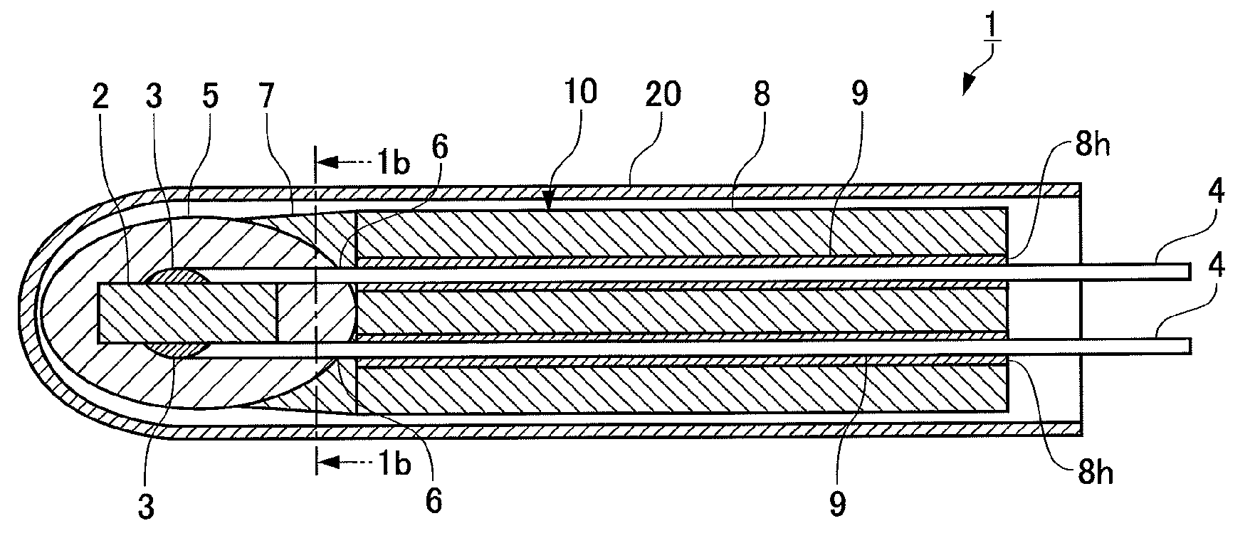
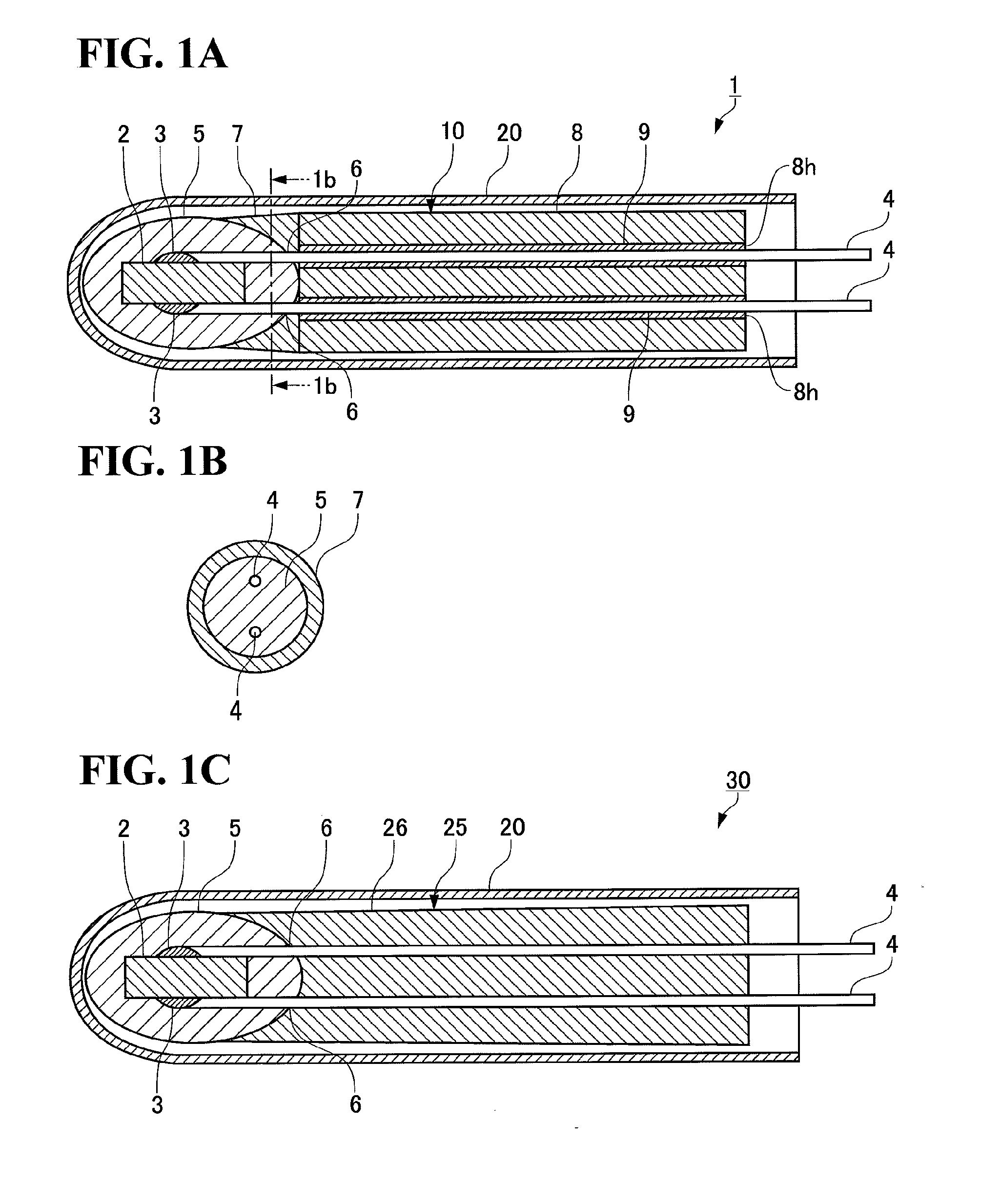
[0038]FIG. 1A shows a temperature sensor 1 of the first embodiment of the present invention.

[0039]The temperature sensor 1 comprises a sensor element unit 10 and a metallic protective tube 20 which houses the sensor element unit 10 except part of the lead wires 4 on the rear side.

[0040]The temperature sensor unit 10 comprises a temperature sensing element 2 whose electrical resistance changes according to the temperature, a pair of lead wires 4 electrically connected to the temperature sensing element 2 via an electrode 3, and a covering material 5 which seals the temperature sensing element 2 and the lead wires 4 in a prescribed range from the electrode 3. The lead wires 4 are taken out of sealed ends 6 of the covering material 5.

[0041]Although it is preferable to use a thermistor as the temperature sensing element 2, temperature sensing elements wh...

second embodiment

[0077]The temperature sensor 30 of FIG. 1C comprises a sensor element unit 25 and a metallic protective tube 20 which houses the sensor element unit 25 except part of the lead wires 4 on the rear side. It can be considered that in the sensor element unit 25, a shield 26 is obtained by integrally fabricating the sealed end closing element 7 and lead wire protective tube 8 of the first embodiment. In the same manner as in the first embodiment, the shield 26 can be formed by supplying a raw material LM made of a ceramic powder and a dispersion media to a prescribed region in a mold and fabricating a molded body, which is thereafter sintered. The same applies also to the third embodiment and the fourth embodiment.

[0078]Also in the senor element unit 25 of this second embodiment, the shield 26 surrounds the rear end side of a covering material 5, encloses sealed ends 6, and protects the lead wires 4.

third embodiment

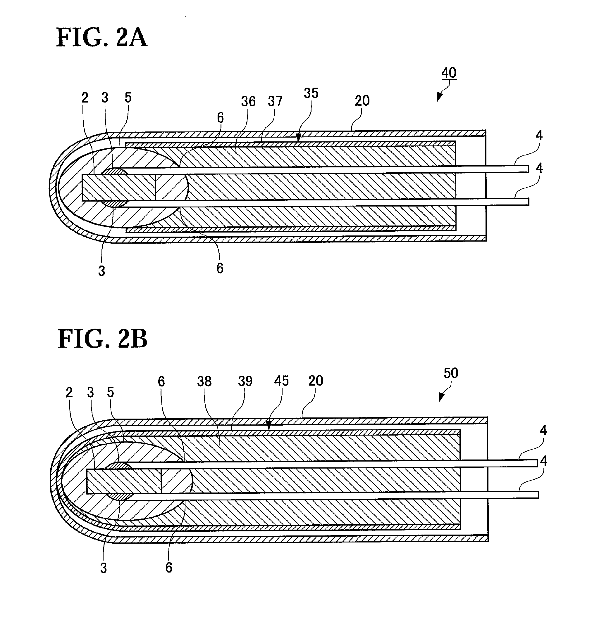
[0079]The temperature sensor 40 of FIG. 2A comprises a sensor element unit 35 and a metallic protective tube 20 which houses the sensor element unit 35.

[0080]The sensor element unit 35 comprises a coated tube 37 made of ceramic which covers a shield 36 similar to the shield 26 of the second embodiment. Also in this sensor element unit 35 of the third embodiment, the shield 36 and the coated tube 37 close sealed ends 6 by surrounding the rear end side of a covering material 5, and protect lead wires 4.


PUM

PropertyMeasurementUnit
temperatureaaaaaaaaaa
porosityaaaaaaaaaa
temperatureaaaaaaaaaa

Abstract

Provided is a temperature sensor capable of stably keeping the accuracy of detected temperatures. The temperature sensor of the present invention comprises a sensor element (1) comprising a temperature sensing element (2) whose electrical resistance changes according to temperature; a pair of lead wires (4) electrically connected to the temperature sensing element (2); and a covering material (5) which seals the temperature sensing element (2) and portions of the lead wires (4) in a prescribed range; wherein the lead wires (4) are led out of the sealed ends (6) of the covering material (5). The temperature sensor further comprises a metallic protective tube (20) which houses the sensor element (1) except part of the lead wires (4); and a shield comprising a ceramic sealed end closing element (7) which encloses the sealed ends (6), and a lead wire protective tube (8). The shield is loosely fitted inside the metallic protective tube (20).

Description

TECHNICAL FIELD[0001]The present invention relates to a temperature sensor provided with a temperature sensing element whose electric resistance changes according to temperature.BACKGROUND ART[0002]A temperature sensor which uses a temperature sensing element whose resistance value changes according to the temperature has been in widespread use in order to measure the temperature of automotive exhaust gas, a water heater, a boiler, a multifunction microwave oven, a stove and the like. As shown in FIG. 11, a temperature sensor element (hereinafter referred to simply as a sensor element) used in this temperature sensor comprises a temperature sensing element 2 provided with a pair of electrodes 3, a lead wire 4 connected to each of the electrodes 3 in pair, and a covering material which seals the temperature sensing element 2. The covering material is made of heat-resistant crystalline glass, amorphous glass or the like. When the sensor element is installed in an electric oven (an ele...

Claims


Application Information

Patent Timeline
Patent Type & Authority Applications(United States)
IPC IPC(8): G01K7/16
CPCG01K1/10G01K7/24G01K1/12
Inventor NAKAYAMA, NORIYUKINAKAMURA, KAZUMASAMISUMI, HIROSHIKOIKE, TERUKAZU
Owner SHIBAURA ELECTRONICS CO LTD
Learn More