Optical fibre connector
- Summary
- Abstract
- Description
- Claims
- Application Information
AI Technical Summary
Benefits of technology
Problems solved by technology
Method used
Image

Examples
Embodiment Construction
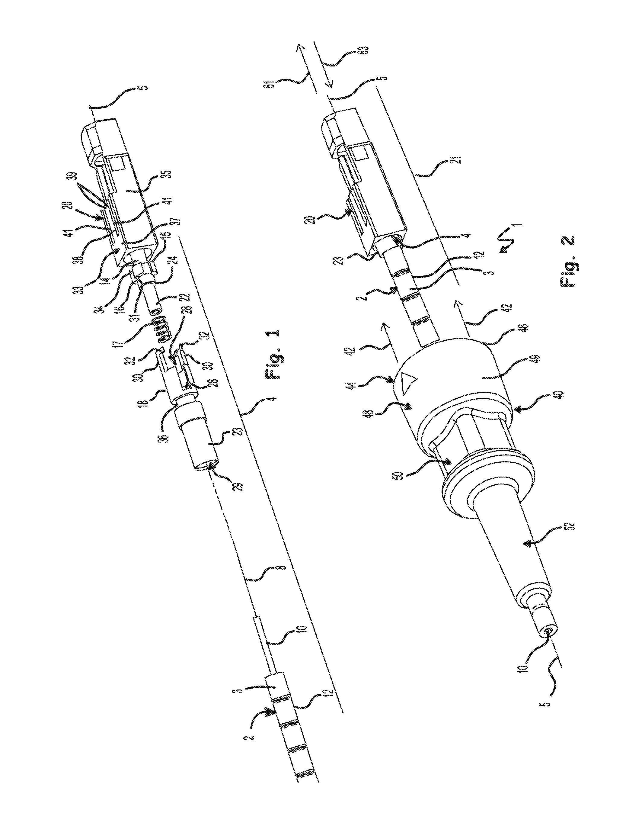
[0051]FIG. 1 shows an exploded view of the components forming a ferrule holder sub-assembly 4 for an optical fibre connector. The ferrule holder sub-assembly 4 is the same as that disclosed in WO 2008 / 135727 A. It should be noted that this particular form of ferrule holder sub-assembly is not the only type of sub-assembly suitable for the invention disclosed herein, and other known types of ferrule holder sub-assembly may equally well be used in its place. The prior art ferrule holder sub-assembly 4 described below is therefore given as one example only in order to aid better understanding of the invention as defined by the scope of the appended claims.
[0052]The ferrule holder sub-assembly 4 comprises an end portion 3 of an optical fibre cable 2. The cable 2 holds a single strand of 125 μm diameter single mode optical fibre 8, protected by primary and secondary buffering layers 10, about 900 μm in diameter and by an outer sheath 12, typically 3 mm to 5 mm in diameter. The optical fi...
PUM
 Abstract
Description
Claims
Application Information
 - Generate Ideas
- Intellectual Property
- Life Sciences
- Materials
- Tech Scout
- Unparalleled Data Quality
- Higher Quality Content
- 60% Fewer Hallucinations
Browse by: Latest US Patents, China's latest patents, Technical Efficacy Thesaurus, Application Domain, Technology Topic, Popular Technical Reports.
© 2025 PatSnap. All rights reserved.Legal|Privacy policy|Modern Slavery Act Transparency Statement|Sitemap|About US| Contact US: help@patsnap.com