
Thermo-electric device

a technology of thermoelectric devices and peltier modules, which is applied in the field of thermoelectric devices, can solve the problems of not being able to meet the needs of primary care environment, not being able to meet the needs of cold hyperalgesia testing on their own, and not being able to meet the needs of peltier modules

Inactive Publication Date: 2012-03-15
THE UNIV OF QUEENSLAND
View PDF9 Cites 12 Cited by
  • Summary
  • Abstract
  • Description
  • Claims
  • Application Information

AI Technical Summary

Benefits of technology

The invention is a thermo-electric device that includes a probe and a Peltier module in thermal contact with each other. The device has a control unit that can heat or cool the probe to a specific temperature range during a test cycle. The device can be powered by a battery and includes a thermal mass that is cooled to a lower temperature limit before the test cycle begins. The device can be used in a handheld unit or in a system with a cold block. The technical effect of the invention is to provide a precise and efficient tool for thermal control in a compact and portable device.

Problems solved by technology

At the present time this is not possible in the primary care environment in which the vast majority of people with whiplash injury are managed.
Peltier modules are not very energy efficient as they draw high amounts of power to provide a large temperature differential between their sides.
Peltier modules have not been considered suitable on their own for cold hyperalgesia testing as the temperature range used in cold hyperalgesia testing would require that the temperature differential of the Peltier module be so large as to require impractical amounts of power to effectively energise the Peltier module.
Because the apparatus of U.S. Pat. No. 5,191,896 comprises a number of separate spaced apart components the apparatus is generally bulky and not suitable for easy transportation.
Connecting the cooling unit to the probe unit by the flow of cooling fluid between the units is complex and lends itself to mechanical breakdown.
Additionally the units are expensive and this is not feasible for use in the clinical environment.

Method used


Image

  • Thermo-electric device
  • Thermo-electric device
  • Thermo-electric device

Examples


Embodiment Construction

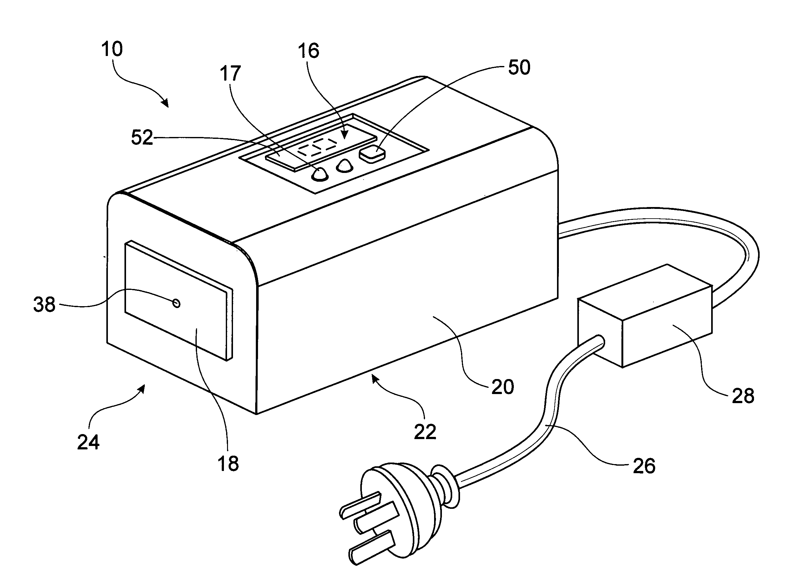
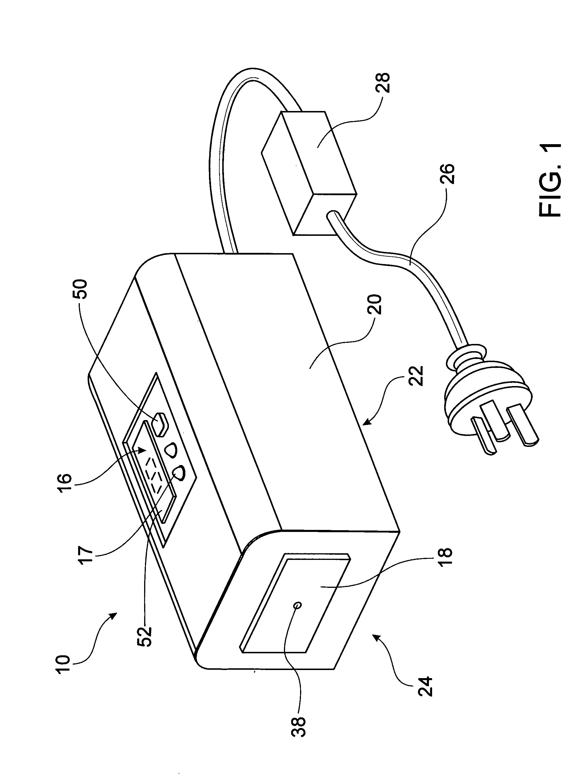
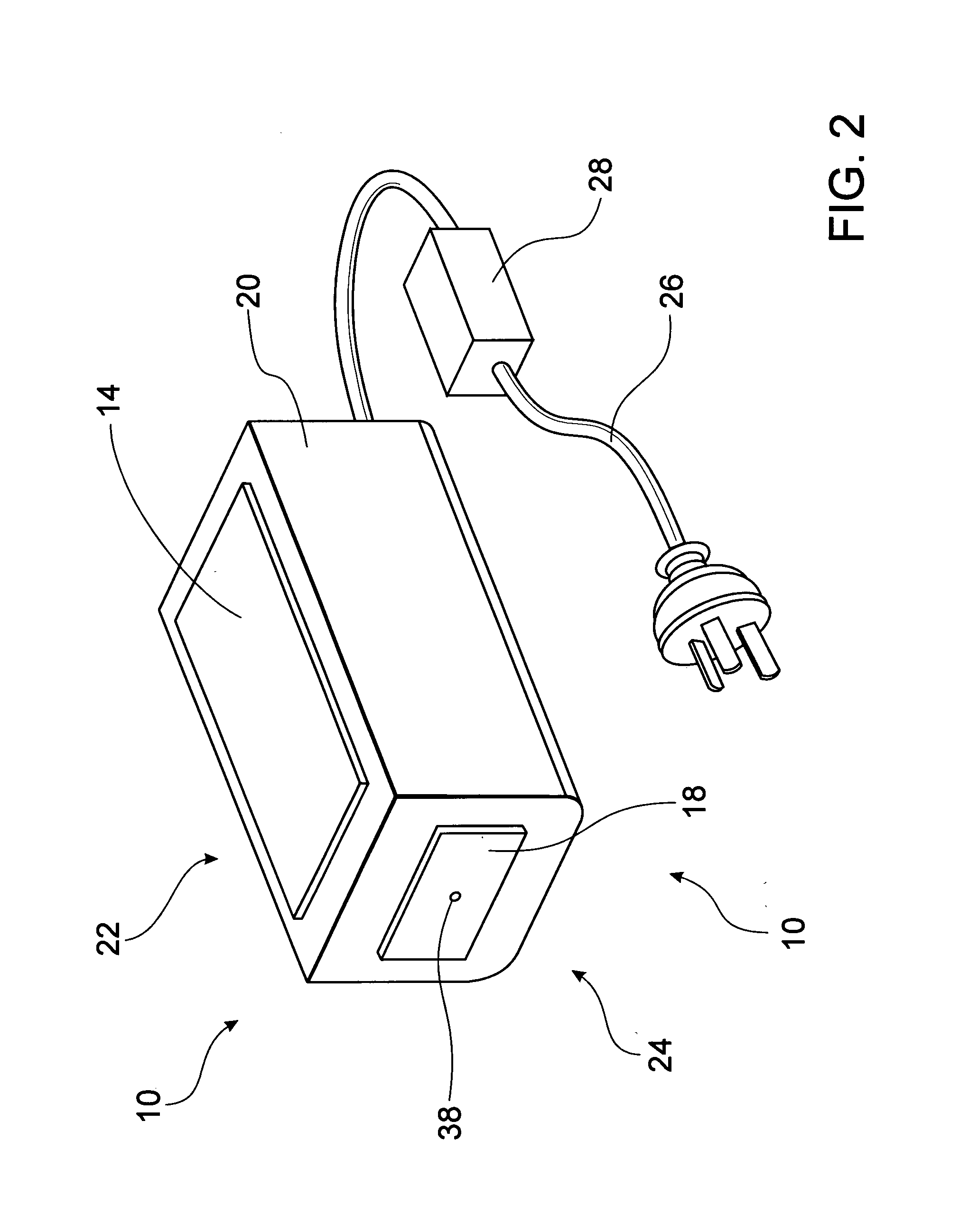
[0039]With reference to FIGS. 1 to 4 of the drawings, one embodiment of a thermo-electric device in accordance with the invention is designated generally by reference numeral 10. The thermo-electric device 10 is a unitary handheld device used for cold hyperalgesia testing. The thermo-electric device 10 includes a thermal mass 14, a control unit 16, a probe 18 and a housing 20. A Peltier module 12 (shown in FIG. 4) is located between the thermal mass 14 and the probe 18.

[0040]The thermal mass 14 is exposed at an underside 22 of the device 10 and the probe 18 is exposed at a front end 24 of the device 10. The thermal mass 14 and probe 18 stand proud from the housing 20.

[0041]Electric power is supplied to the control unit 16 from mains electricity via a power cord 26 and a transformer 28.

[0042]Referring to FIG. 3, the thermal mass 14 is cooled by placing the device 10 on a cold block 30. The cold block 30 is a block of aluminium material. The cold block 30 is pre-cooled by being placed...


PUM


Abstract

A portable handheld thermo-electric device (10) is used to test for decreased cold pain thresholds or increased sensitivity to cold stimulation (cold hyperalgesia) in a patient. The thermo-electric device (10) comprises a probe (18), a Peltier module (12) and a control unit (16) operable to energize the Peltier module (12) so that the temperature of the probe 18 is variable in a range between a predetermined upper temperature limit and a predetermined lower temperature limit during a test cycle of the thermo-electric device (10). A thermal mass (14) is adapted for thermal contact with an interface side (34) of the Peltier module (12). The Peltier module (12) has thermal properties which enables it to be cooled to a temperature below the predetermined upper temperature limit and thereafter maintain the interface side (34) of the Peltier module (12) at a temperature below the predetermined upper temperature limit for the duration of the test cycle.

Description

FIELD OF THE INVENTION[0001]The invention relates to a thermo-electric device. In particular, although not exclusively, the invention relates to a portable handheld thermo-electric device for affecting a temperature drop on the skin as an indicator of decreased cold pain thresholds or increased sensitivity to cold stimulation (cold hyperalgesia) in a patient.BACKGROUND TO THE INVENTION[0002]Cold hyperalgesia (or decreased cold pain threshold) is a feature of some musculoskeletal pain conditions and is thought to reflect changes in central nervous system pain processing mechanisms. In the case of whiplash injury (that is neck pain following a motor vehicle crash) the presence of cold hyperalgesia is important as this feature has been shown to be predictive of poor functional recovery and be associated with non-responsiveness to standard physical interventions, e.g. exercise.[0003]The early identification of whiplash injured people at risk of poor recovery is important for several rea...

Claims


Application Information

Patent Timeline
Patent Type & Authority Applications(United States)
IPC IPC(8): A61F7/00H10N10/13
CPCA61B5/01A61B5/4824A61F7/007A61F2007/0075A61F2007/0096A61F2007/0081A61F2007/0086A61F2007/0093A61F2007/008A61F2007/0011
Inventor GREAVES, MATTHEW CAMPBELLSTERLING, MICHELE
Owner THE UNIV OF QUEENSLAND
Learn More